THETA
Telecom-native Hybrid Eight-bit Transdimensional Architecture
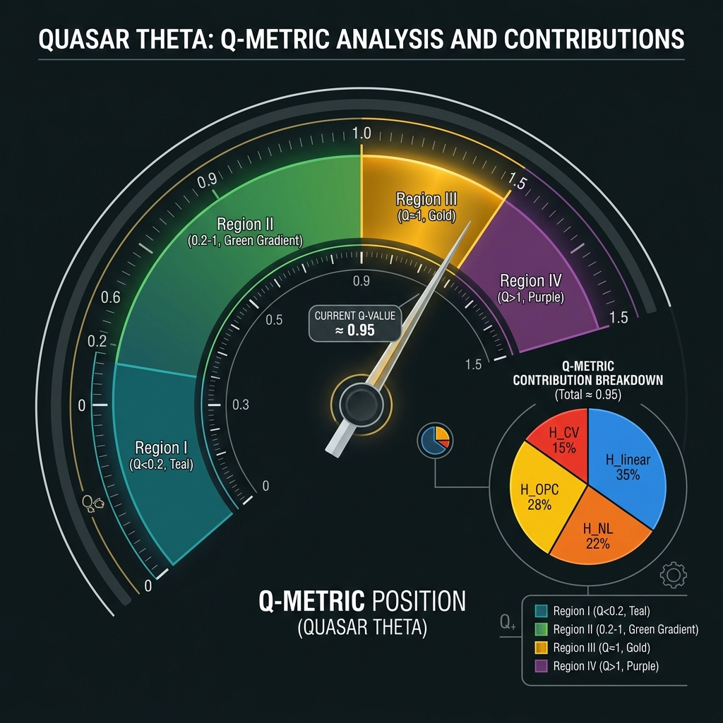
QUASAR · d=256=2⁸ · GF(256) · Region III · Q ≈ 1
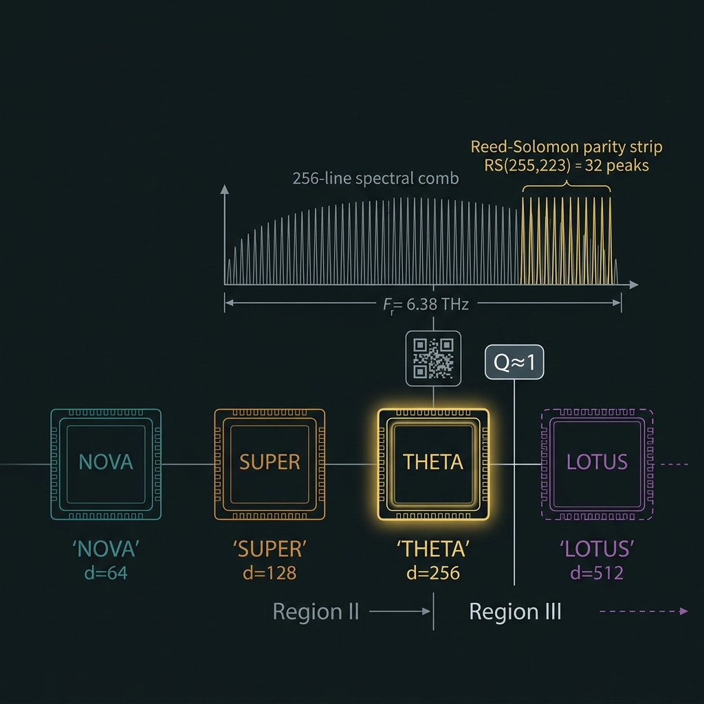
THETA is QLT's first plausible field-computing architecture — a d=256=2⁸ frequency-bin qudit on GF(256) = GF(2⁸) at Δf = 25 GHz and Bcomb = 6.38 THz, deliberately telecom-native so RS(255,223) and QR-code symbol algebra align byte-for-byte with the photonic carrier. It operates at the Region III Q ≈ 1 boundary where nonlinear OPC + CV dynamics co-equal linear routing — experimental research, not a shipping product, but the first chip where classical coding theory and quantum field control share one 8-bit symbol layer.
At Q ≈ 1, HNL + HOPC + HCV ≈ Hlinear. THETA is not a linear processor with OPC hygiene (NOVA); it is a field-computing machine where conjugation and squeeze define the compute model. First QUASAR chip where Bcomb consumes ~53% of the 12 THz OPC band (~1.9× margin).
THETA specification ledger
Canonical numbers from WS13 Δf table and S61–S70 corpus.
Q = (H_NL + H_OPC + H_CV) / H_linear

Region I (STAR-PHASER):  Q < 0.2
Region II (QUASAR):      0.2 – 1
Region III:              Q ≈ 0.85–1.05  ← THETA

H_linear ≈ 0.35 · H_NL ≈ 0.22
H_OPC ≈ 0.28 · H_CV ≈ 0.15
Lineage: NOVA (d=64, Region II) → SUPER (d=128) → THETA (d=256, Region III) → LOTUS (d=512, Region IV).
| Property | Value | Status |
|---|---|---|
| Hilbert dimension d | 256 = 2⁸ | designed/target |
| Algebraic layer | GF(256) = GF(2⁸), char 2 | external math |
| Bits / photon | 8 | info-theoretic |
| Comb spacing Δf | 25 GHz | designed/target |
| Comb span Bcomb | 6.38 THz (255×Δf) | model |
| OPC bandwidth margin | ~1.9× @ 12 THz | model |
| Phase relationships | 65,280 (=256×255) | model |
| Default RS block | RS(255,223), t=16 | designed/target |
| Octet tiling | 8×32 | designed/target |
| First OPC-band stress | Bcomb > 50% of 12 THz | flagged |
| Program class | Experimental research | post-NOVA/SUPER |
 IMG-T01 · Hero
Telecom-native field computing at Q≈1
From GF(64) niche to industry-standard 8-bit byte field.
QUASAR ladder · Rung 5
NOVA → SUPER → THETA → LOTUSNOVA — d=64, Region II, Q ≈ 0.2–0.6
→WS12 synthesis target; RS(63,55) over GF(64). Mature but non-standard for consumer ECC. Algebraic compute pilot with periodic OPC inserts.
d=64 · B_comb=3.15 THz · OPC margin ~4×
SUPER — STAR-PHASER crisis approaches
→Region II at Q ≈ 0.5–0.8. Where linear + periodic OPC paradigm breaks — THETA requires continuous OPC + global phase.
THETA — d=256, Region III, Q ≈ 1
→Hero claim: Industry-standard 8-bit field arithmetic at telecom C-band scale — RS(255,223) block codes native on the carrier. Every syndrome register is a GF(256) byte — interoperable with Berlekamp–Massey IP.
GF(256) ≅ GF(2)[x]/(x⁸+x⁴+x³+x²+1)   [0x11B]
|f_k⟩ ↔ α^k, k = 0…254 active; bin 255 guard
LOTUS — Region IV, CV-primary extreme
→Extreme coherent spectral machine; Q > 1. THETA stays field-structured; LOTUS is CV-primary. THETA is OPC-margin corner solution, not LOTUS-scale.
 IMG-T02
Industry-standard byte field
- RS(255,223) — DVB-S2, DOCSIS, space links
- QR codes — ISO/IEC 18004 GF(256) Reed–Solomon
- Storage — Blu-ray, flash ECC outer codes
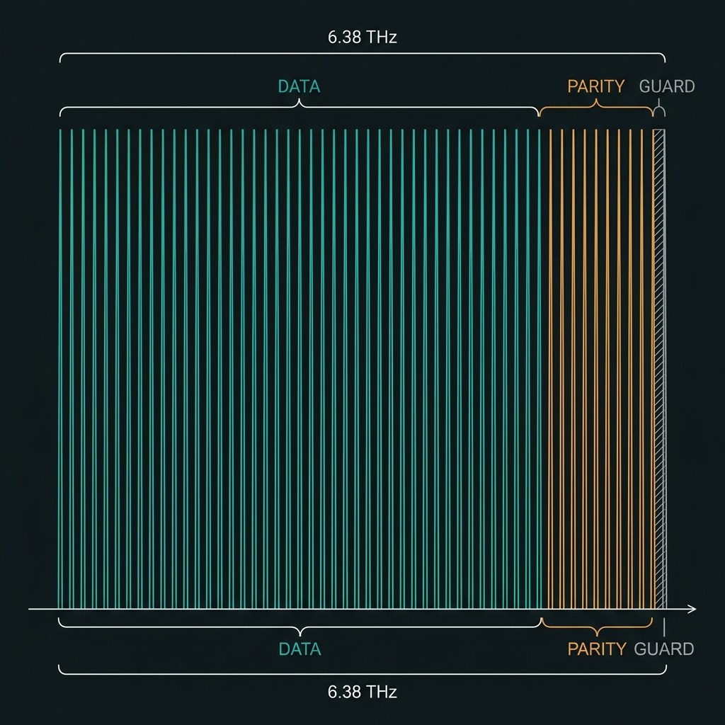
256-bin lattice & RS(255,223) / QR alignment
Classical ECC test vectors as native physical states.
f_k = f_ref + k·Δf,  k = 0…255
Δf = 25 GHz
B_comb = 255·25 GHz = 6.38 THz
OPC fraction: ~53% → ~1.9× margin
Active bins α⁰…α²⁵⁴; bin 255 monitors wrap-around α²⁵⁵ = α⁰. Primitive polynomial 0x11B fused at fab for QR/AES interop.
Default compute register code
n=255, k=223, 2t=32 parity. t=16 random symbol errors; up to 32 erasures with heralded loss. Syndrome S_j ∈ GF(256) — field register, not bin index.
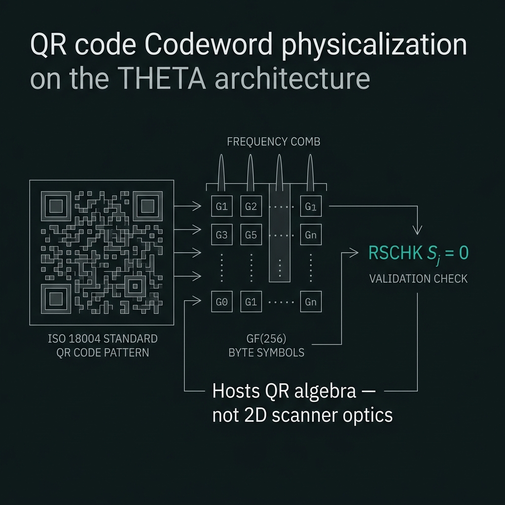
QR alignment: Version 40-L codeword inject → RSCHK S_j = 0 [T-THETA-QR]. Hosts QR algebra — not 2D scanner optics.
 IMG-T03
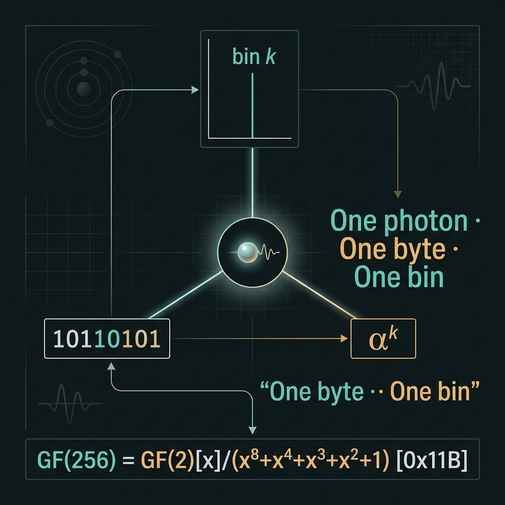 IMG-T04
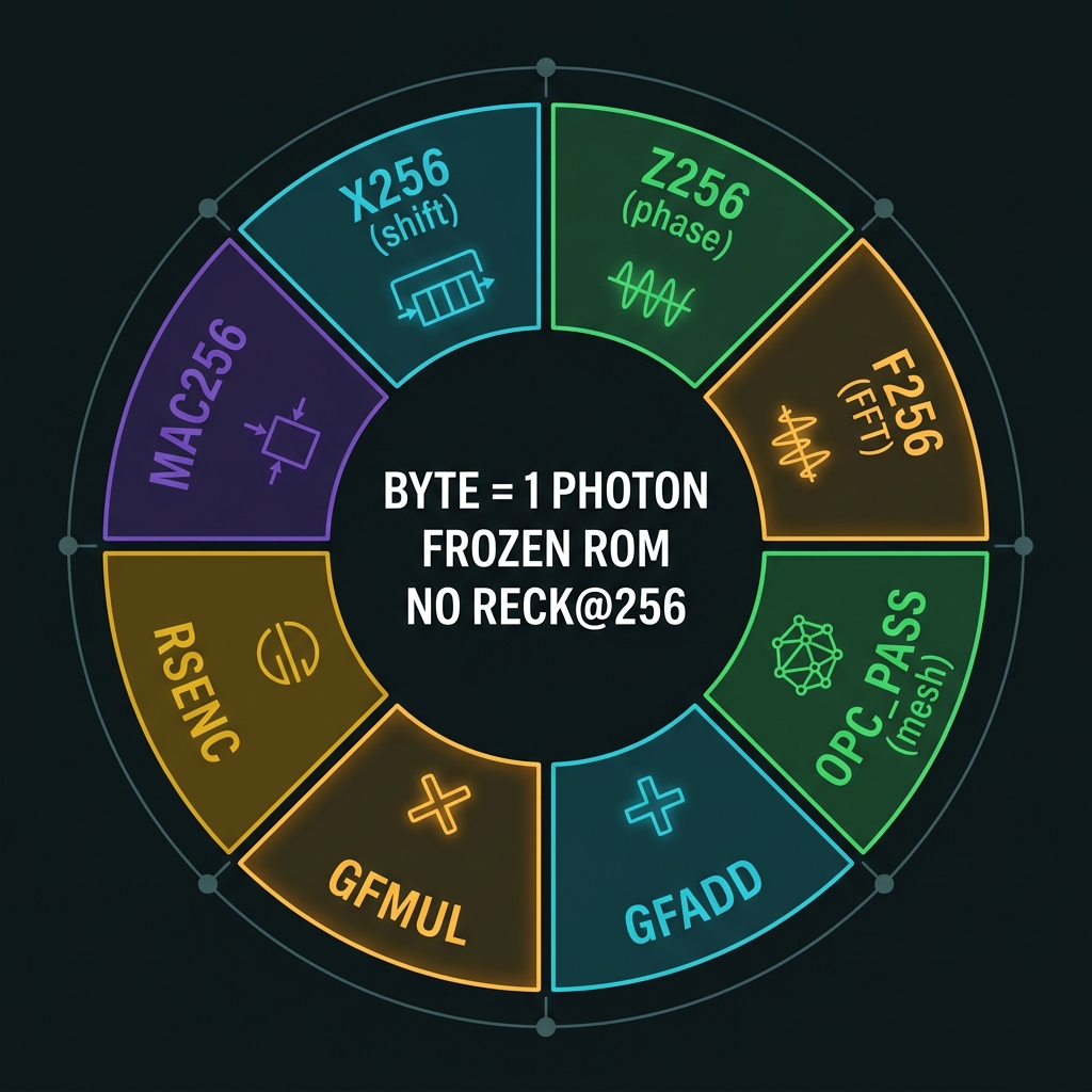
8-bit symbolic ISA — frozen Tier-A
Reck SU(256) ~32k MZIs rejected; ~2k frozen cells selected.
| X₂₅₆ | Cyclic bin shift | 4 cycles |
| Z₂₅₆ | Diagonal ω^k | 2 cycles |
| F₂₅₆ | Radix-8 FFT, 128 stages | GFMUL enabler |
| OPC_PASS | Mesh refresh opcode | Every 4–8 field ops |
| GFADD | XOR on 8-bit poly | 8 depth |
| GFMUL | F₂₅₆ convolution | 16 depth |
| RSENC | 255 MAC parity | 255 cycles |
| MAC256 | GF(256) inner product | 32 cycles |
 IMG-T05
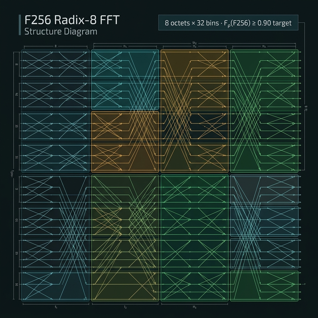 IMG-T06
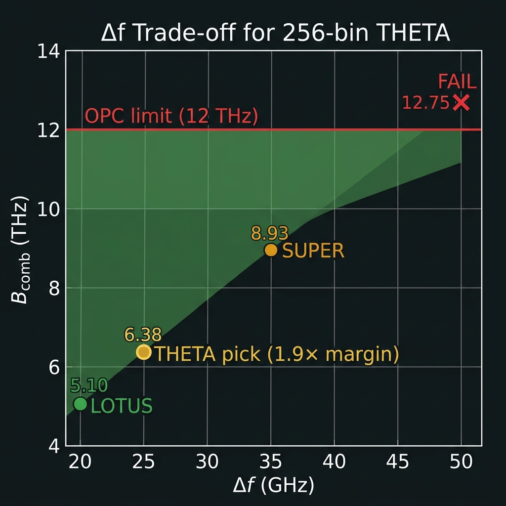
Δf trade vs 12 THz OPC band
First QUASAR source where comb width consumes ~53% of OPC acceptance.
| 50 GHz | B_comb = 12.75 THz | <1× FAIL |
| 35 GHz | 8.93 THz | 1.34× — SUPER territory |
| 25 GHz ✓ | 6.38 THz | ~1.9× — THETA pick |
| 20 GHz | 5.10 THz | 2.35× — LOTUS default |
256-line source architecture
Octet subcombs · multi-tile · ~18×24 mm²Phase-locked octet subcombs
→OCT_i: 32 lines, span 775 GHz Global: 8 octets × 775 GHz = 6.2 THz + guard gaps Lock: common 25 GHz f_rep, per-octet CEO trim
Ring R ≈ 960 µm for 25 GHz FSR. Watt-class CW pump; TFLN EO sideband lock to 25 GHz PLL.
Multi-layer heterogeneous stack
→L1 Si₃N₄ core routing · L2 TFLN bond EO/QFP · L3 As₂S₃/AlGaAs FWM-OPC mesh · L4 Ge PD/SPAD · L5 heater metal (256+ trims). Target σ_power < 1 dB across comb.
Stitched multi-die floorplan
→SRC-0…7 (8×3×4 mm²) · QFP-CORE (6×8 mm²) · OPC-MESH (4×6 mm²) · RD-256 (4×4 mm²). Total ~18×24 mm² [model].
 IMG-T07
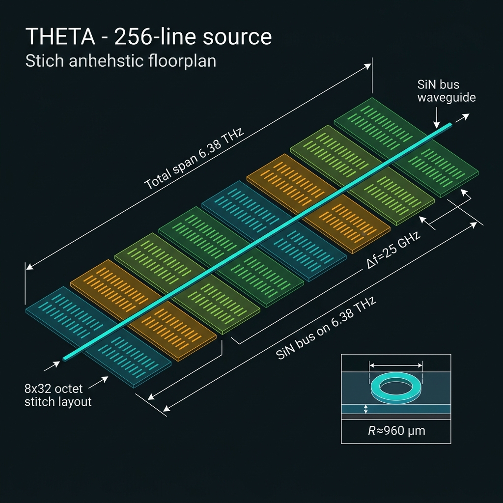 IMG-T08
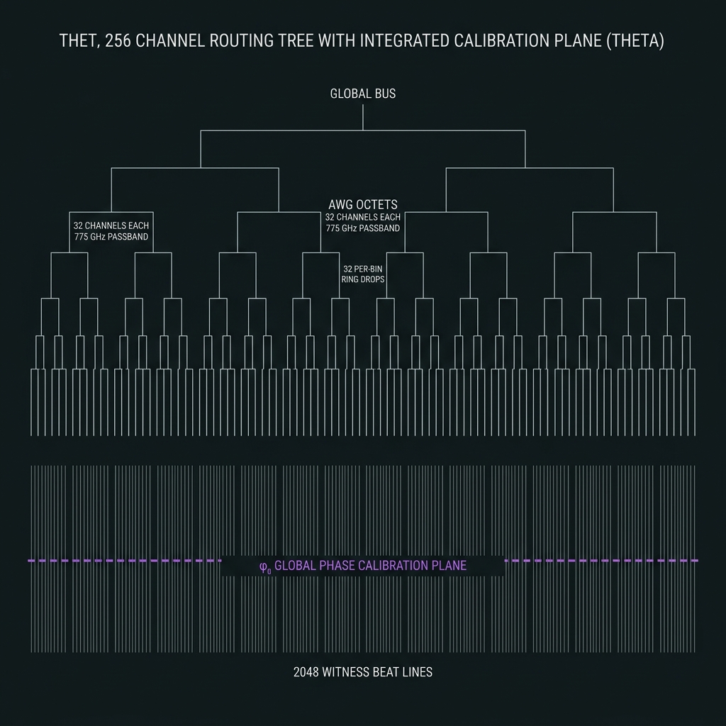
256-ch tree + calibration plane
Routing and calibration merge at d=256 — global gauge drift masquerades as field dynamics.
Tier 0: Global bus waveguide (single mode)
Tier 1: 8 × octet AWG (32 ch, 775 GHz passband)
Tier 2: 32 × per-bin ring drop/add (within octet)
Δλ per bin @ 1550 nm ≈ 0.20 nm. Adjacent crosstalk < −20 dB target. Frozen mask + heater trim — no runtime AWG.
Parallel hardware path beneath data plane: GPS-RF heterodyne → f_ref absolute; φ₀ loop on all 256 bins @ 10 kHz; 8 octet trims @ 1 kHz; ~2,048 sparse witness beats per refresh.
φ₀ loop absorbs global gauge without corrupting relative φ_{ij} — mandatory for F₂₅₆ and GFMUL convolution semantics.
 IMG-T09
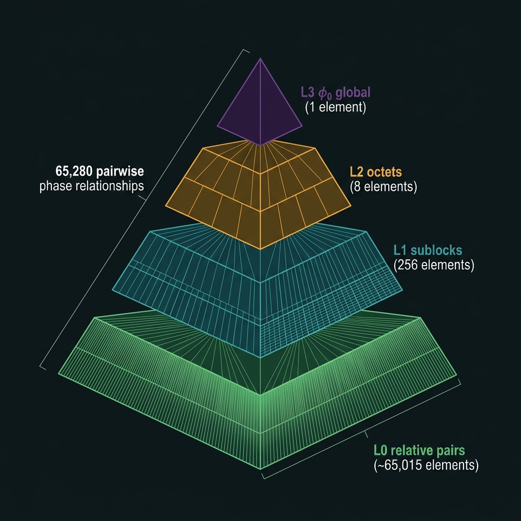 IMG-T10
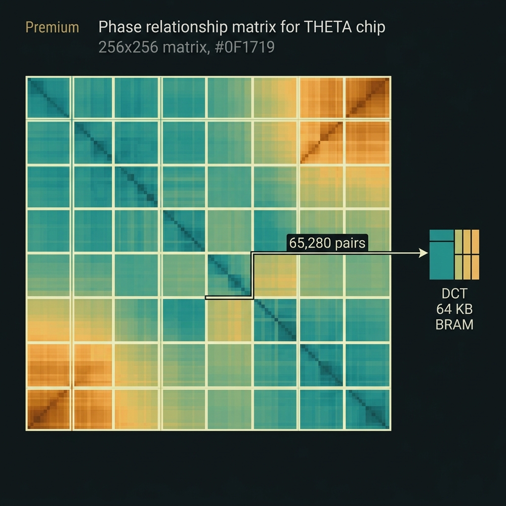
65,280 phase relationships
ChiL hierarchical locking + sparse witness inference — compression mandatory at 16× NOVA pair count.
N_pairs = d·(d−1) = 256·255 = 65,280 directed pairwise phase relationships
Target residual: σ_φ ≤ 0.08 rad rms on 95% of pairs → GFMUL F_ρ ≥ 0.92
| TETRIS d=32 | 992 | 160 sparse |
| NOVA d=64 | 4,032 | 512 sparse |
| SUPER d=128 | 16,256 | 1,024 sparse |
| THETA d=256 | 65,280 | ~2,048 sparse |
| LOTUS d=512 | 261,632 | ~4,096 |
BOOT → COMB_LOCK → φ₀_LOCK → ChiL_L3→L2→L1
  → WITNESS_2048 → INFER_65280 → F256_PROBE
  → GFMUL_PROBE → RSCHK_ZERO → RUN
  ↺ (every 30 s or OPC alarm)
PHASE_TABLE compressed to 64 KB DCT coeffs in FPGA BRAM — raw 2.6 MB rejected on-die.
 IMG-T11
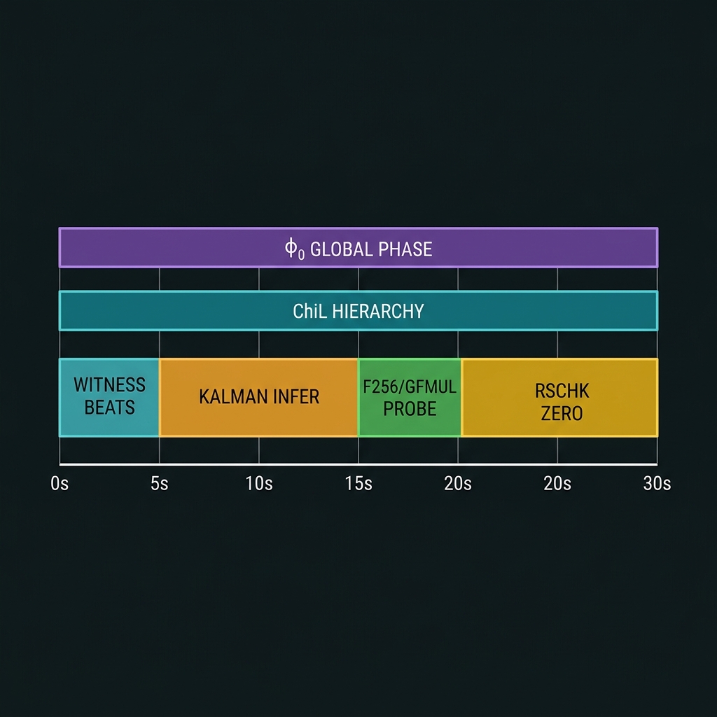 IMG-T12
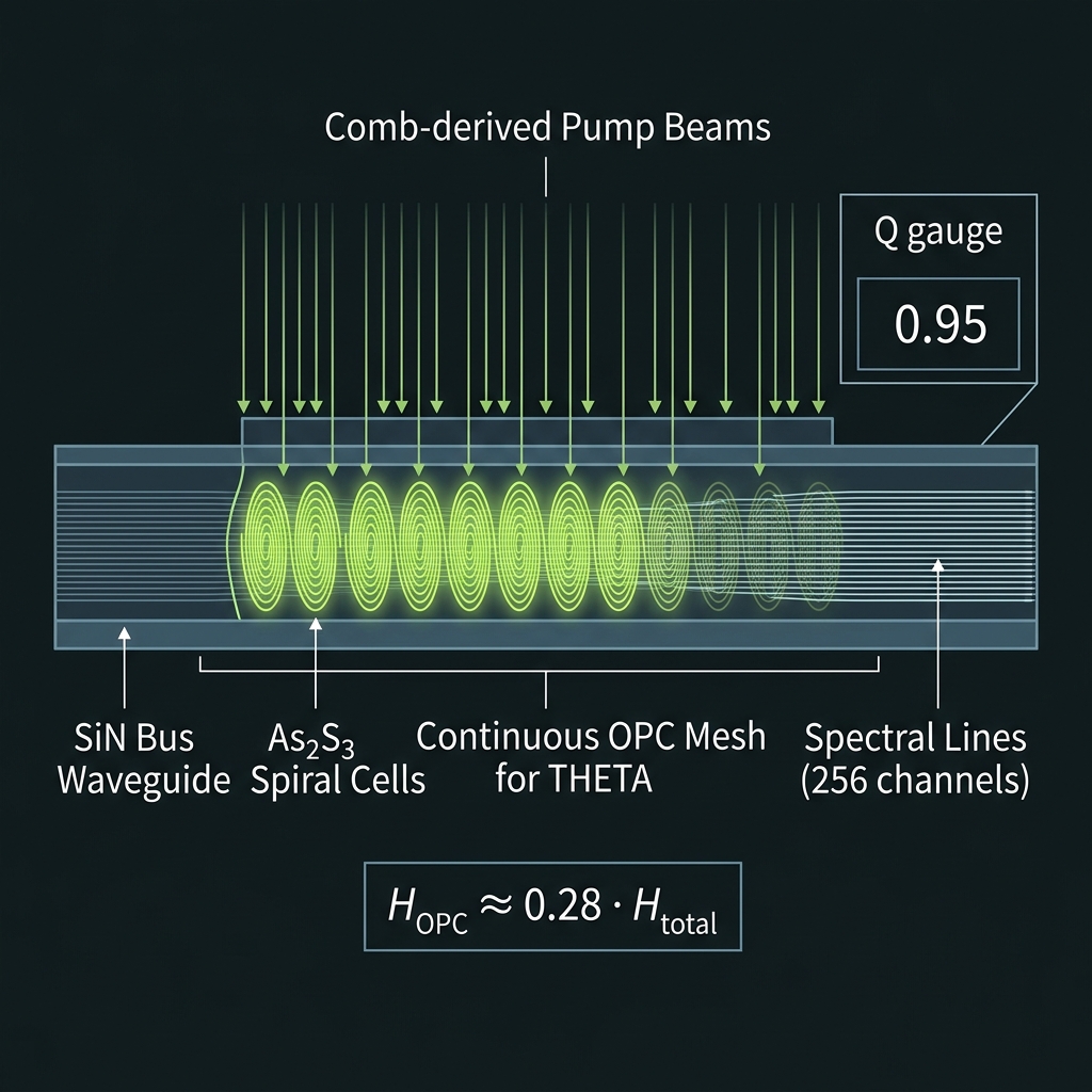
Continuous conjugation mesh — architecture, not hygiene
First QUASAR chip where OPC is co-primary with linear routing at Q≈1.
| Placement | Every M=10 gates | Continuous mesh |
| H_OPC/H_linear | 0.1–0.3 | ~0.25–0.35 |
| Squeezing | Recommended | Mandatory ≥6–10 dB |
| B_comb vs OPC | 3.15 THz (~4×) | 6.38 THz (~1.9×) |
16–32 As₂S₃/AlGaAs spiral cells along bus waveguide, always-on at duty-cycled pump. η per cell 0.5–2% CW; L_eff ~40–55 mm per cell. Comb-derived multi-pump (G45 ×4) — 32 active pumps per cycle from 256 candidates.
η(ω) flatness target ±15% across 6.38 THz. Single-photon OPC [to-be-tested] — campaign milestone #1; bright-light signoff → 8-bin subset tomography → scale to 256.
 IMG-T13 · Required
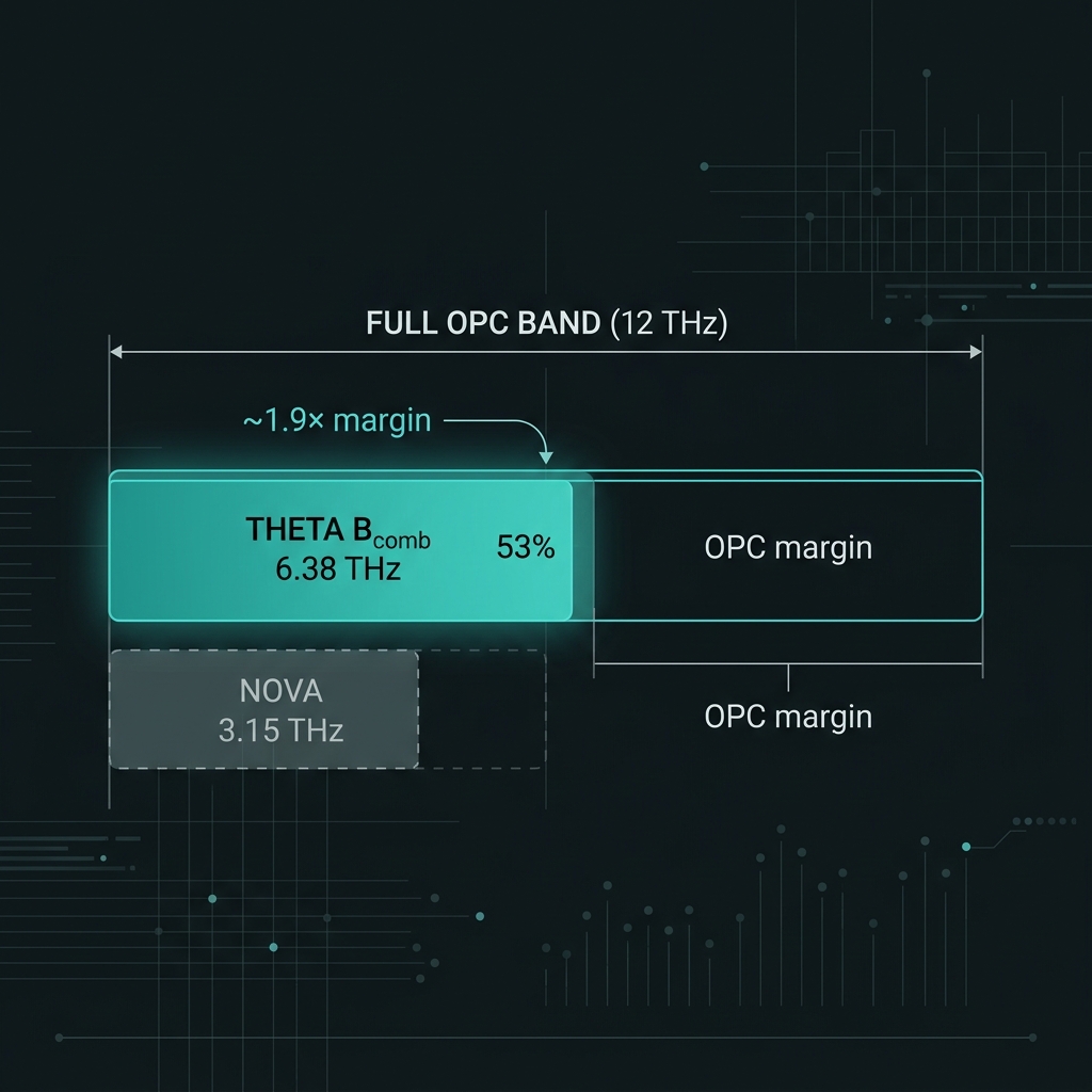 IMG-T14
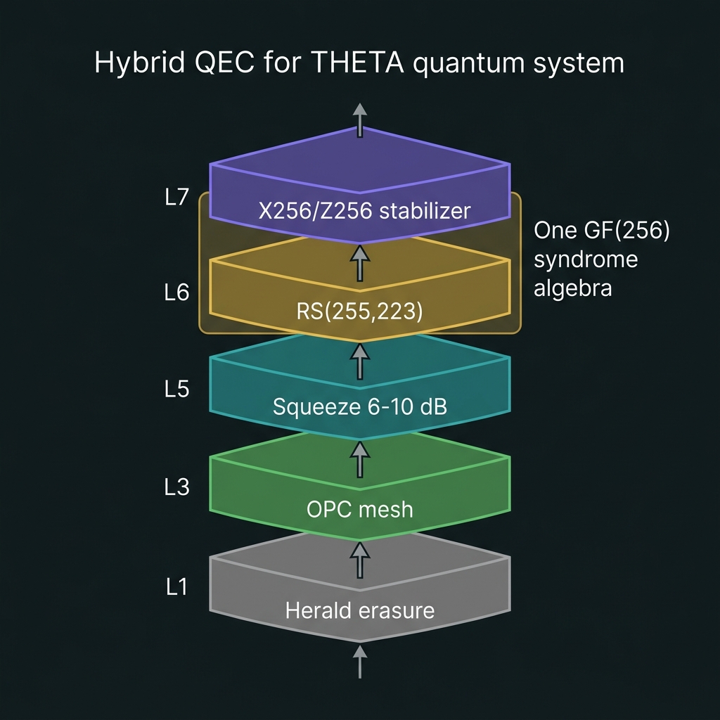
Photonic-native classical+quantum hybrid ECC
RS(255,223) and X₂₅₆/Z₂₅₆ stabilizers share one GF(256) syndrome algebra.
| L1 Loss | Herald erasure → RS decode |
| L3–4 OPC | Continuous mesh phase pre-correction |
| L5 CV | Mandatory 6–10 dB squeeze |
| L6 Classical | RS(255,223), BCH, LDPC over GF(256) |
| L7 Quantum | X₂₅₆/Z₂₅₆ stabilizer rounds |
1. OPC_PASS (continuous mesh refresh)
2. SQUEEZE_OCT (CV witness)
3. RSCHK → syndromes S_j ∈ GF(256)
4. RSDEC (FPGA BM) → error locations
5. RSFIX (photonic XOR)
6. Stabilizer syndrome (X₂₅₆/Z₂₅₆)
7. Pauli frame update
8. RSENC refresh (if drift epoch)
Post-OPC p_Z ~0.01–0.03 [model]; post-RS logical symbol error ~10⁻⁴–10⁻⁶. OPC does not correct loss or bit-flips — RS required.
 IMG-T15
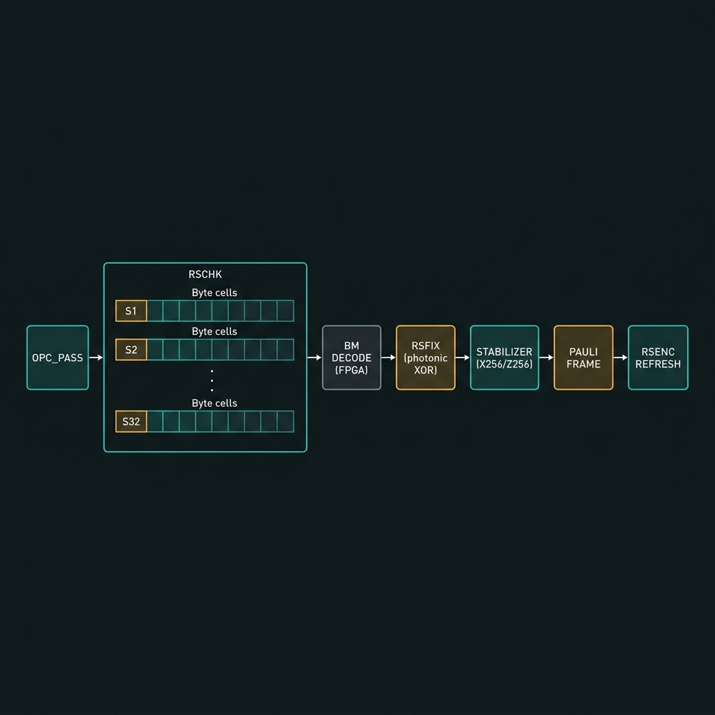 IMG-T16
Honest posture: No claim of fault-tolerant quantum memory at THETA v1. Target is demonstrated hybrid advantage — RS(255,223) codeword recovery @ p_erase < 0.1 [T-THETA-QEC-01]. Stabilizer break-even vs bare register [roadmap].
Coding-theory-aligned field computing
Workloads where GF(256) bytes are native physical symbols — not generic quantum supremacy circuits.
Experimental research workloads
RS streaming · QR hosting · MAC · telecom interopRS(255,223) live encode/decode streaming
→Host bytes → GF(256) inject → RSENC photonic → channel → RSCHK → BM fix. Parity computed in flight on photons. Target ~111k symbols/s, >70% photon survival per block [model].
QR codeword physicalization
→Version 40-L codeword inject → measure bin populations → electronic RSCHK confirms S_j = 0 [T-THETA-QR]. Algebraic layer only — not camera optics.
GF(256) MAC256 optical command authentication
→tag = Σ GFMUL(hᵢ, mᵢ) over GF(256). Host AES-256/ED25519 stays on MCU [G22 firewall] — THETA provides field MAC for optical command auth.
Telecom OTN/FEC testbed
→8-bit symbol source compatible with DVB/DOCSIS RS toolchain — same test vectors as broadcast industry. Electronic decoder uses standard libfec.
 IMG-T17
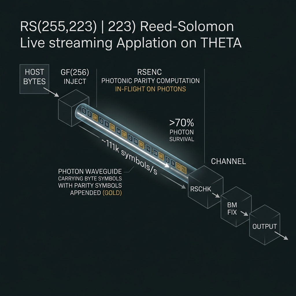 IMG-T18
Bill of materials + control stack
Every component in the THETA d=256 module — photonics, active devices, detectors, electronics, lasers, materials — with vendor sourcing and foundry split across four tiles.
4-tile split-fab module
FEOL: LIGENTEC AN800 — stoichiometric Si₃N₄ + deuterated routing, 256-line microcomb (8×32 octet subcombs), 256-ch AWG tree, ~2,000 frozen QFP cells, octet stitch floorplan. Encrypted GDS-II.
BEOL: QLT internal — continuous OPC mesh (As₂S₃/AlGaAs ×16–32, always-on Leff ~40–55 mm), squeezing + homodyne per octet, SPAD + Ge PD (L4).
Bond: QLT — TFLN TW-EOM (>110 GHz, 16-harmonic RF), heterobond L2 layer.
Backup foundry: AIM/KOTURA (cross-qualification per R18 memos).
First multi-tile module (4 tiles, ~18×24 mm²)
Deuterated SiN: Ultra-low-loss routing [A717] — first chip to use deuterated nitride for inter-tile waveguides.
Always-on OPC: Continuous mesh (process, not event) — As₂S₃/AlGaAs ×16–32 cells, η 0.5–2% CW. OPC margin ~1.9×.
Comb-derived multi-pump: G45 ×4 architecture, 32 active pumps per cycle — major escalation from NOVA's single-pump scheme.
Primitive polynomial: 0x11B (GF(256)) chosen for QR/AES interop — industry-standard field representation.
Same split-fab: LIGENTEC AN800 primary, AIM/KOTURA backup. FEOL/BEOL/Bond split preserved.
LUV language → QIL middleware → Versal FPGA + multi-die ASIC → photonic module
The full control stack from user code to photon — scaled to 256 phase channels with DCT-compressed phase tables and multi-die ASIC coordination.
.luv source → run_freqbin_shot → QIL IR bundle → THETA ISA dispatch (GF(2⁸) ops, RS(255,223), QR)
dac.voltages[256+] → ~2,000 frozen QFP phases → DCT-compressed PHASE_TABLE (64 KB BRAM)qfp_schedule[] → octet-parallel unitary / phase_mask / permute steps (8×32 decomposition)shot_contract → SPAD herald pattern + homodyne readout + post-selection probability
Santec TSL-570 CW pump (1550 nm) · Menlo C-fiber clock (100 MHz, 150 fs)
SPAD + Ge PD readout · homodyne detector per octet
256-ch AWG tree · ~2,000 frozen QFP cells · continuous OPC mesh (Leff ~40–55 mm) · TFLN TW-EOM (>110 GHz)
From THETA to the full QUASAR ladder
THETA is Rung 5 — the Region III field-computing boundary. See today's dual-rail platform, the GF(64) roadmap, and manufacturing path.