The path from Base 2 to GF(256)
A forward vision for Spectral Decimal Computing — from today's base-2 dual-rail through native base-10 frequency-bin arithmetic on the Decimal Quantum Frequency Processor (DQFP) — climbing to GF(64) = GF(2⁶), GF(128) = GF(2⁷) on QUASAR SUPER, and CV/DV GF(256) = GF(2⁸) byte-native field coding on QUASAR THETA. Squeezed-light hybrid readout becomes co-primary above GF(64); a nine-layer preservation stack and comb-derived OPC — continuous mesh at scale — on the same Si₃N₄ / TFLN / As₂S₃ platform.
Base-2 → Base-10 → GF(64) → GF(256)
Six rungs. One photon. Increasing dimension — not increasing wire count.
Tap or hover any rung to expand. GF(64/128/256) are characteristic-2 finite fields for coding and algebra — distinct from decimal base-10 arithmetic. Rungs R4–R5 are Roadmap / Speculative.
Encoding progression
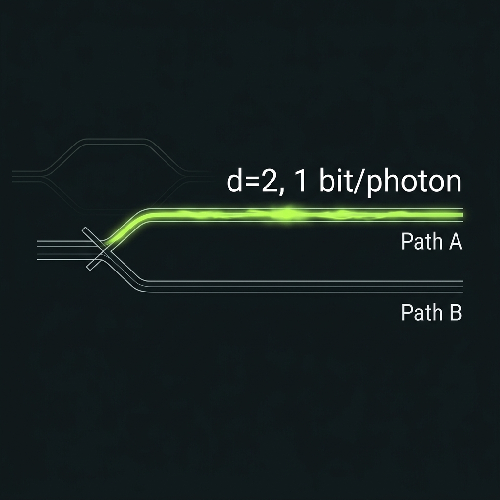
Rungs 0–5 · dimension lift on one spatial modeBase-2 dual-rail qubit
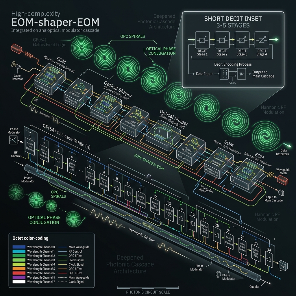
→One photon in one of two Si₃N₄ waveguides: |ψ⟩ = α|path A⟩ + β|path B⟩. Hilbert space ℂ², 1 bit/photon. The v1 shipping design: 8-mode Clements mesh, measurement-based fusion, periodic OPC lattice.
d=2 · SU(2) · dual-rail Sagnac OPC demo path
How we do it: Same platform documented on How We Do It. Dual-rail is the seed for GAP04 transcoding at the encoding boundary.
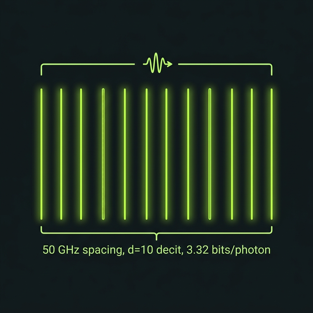
Base-10 frequency-bin "decit"
→Transcode path → color (GAP04), then open the comb: |ψ⟩ = Σ_{n=0}^{9} c_n|f_n⟩. Native decimal digit 0…9 without binary decomposition. log₂10 ≈ 3.322 bits/photon. SU(10) gates via EOM + pulse-shaper quantum frequency processor.
D=10 carrier demonstrated externally (Kues 2017) · QLT integration roadmap
How we do it: 50 GHz comb spacing, 10-ring shaper SPU, TFLN EOM FAU, 10-ch WDM demux. OPC at every boundary conjugates all ten colors in one >12 THz pass.
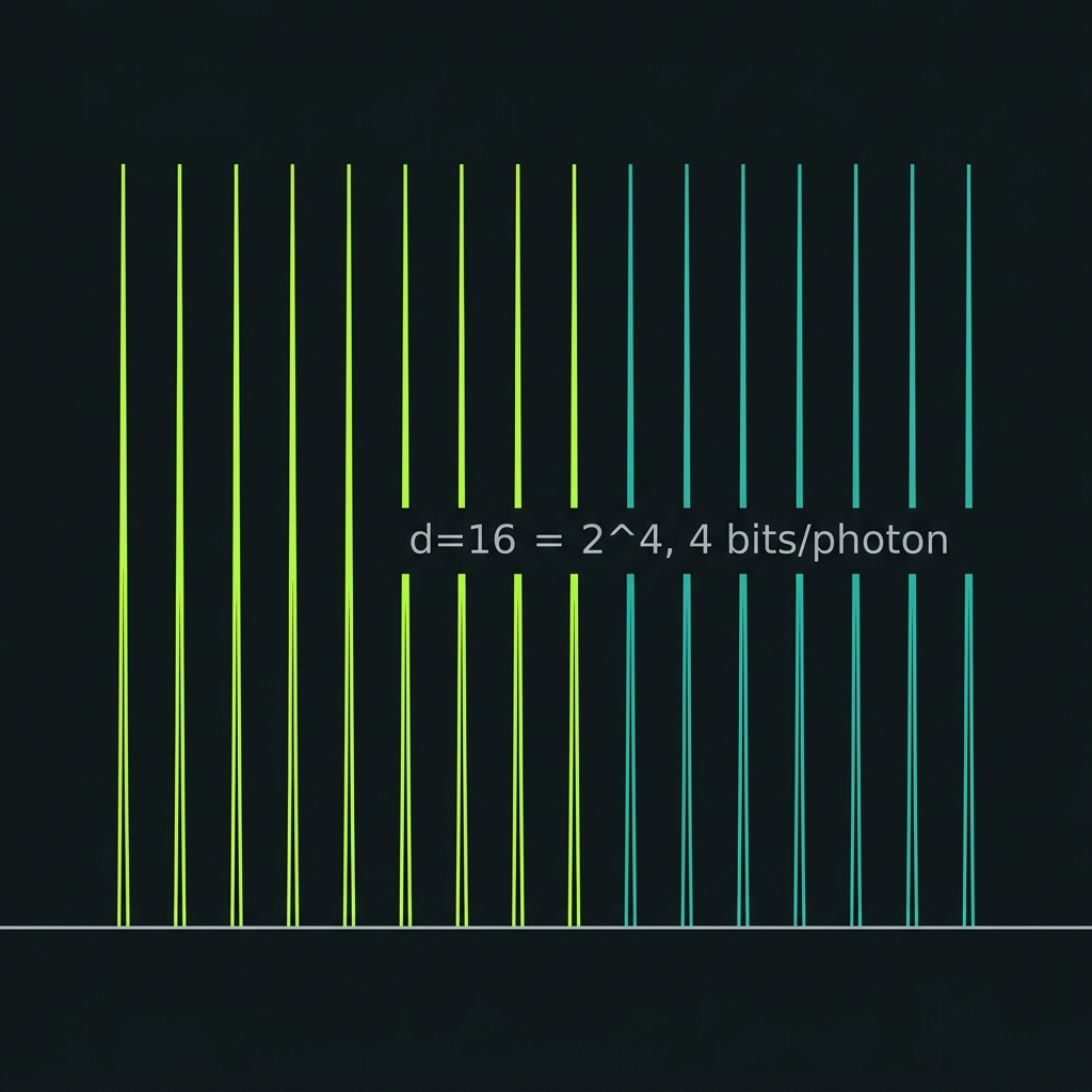
d=16 qudit (GF(16) engine)
→Scale to d=16 = 2⁴ — four bits/photon with cleaner qudit-QEC and mutually-unbiased-basis structure than d=10 (ℤ₁₀ is a ring, not a field). Decimal I/O via transcoder at the application layer (G04).
How we do it: Same QFP stack with 16-ring shaper bank; octet tiling begins here before full 64-line scaling.
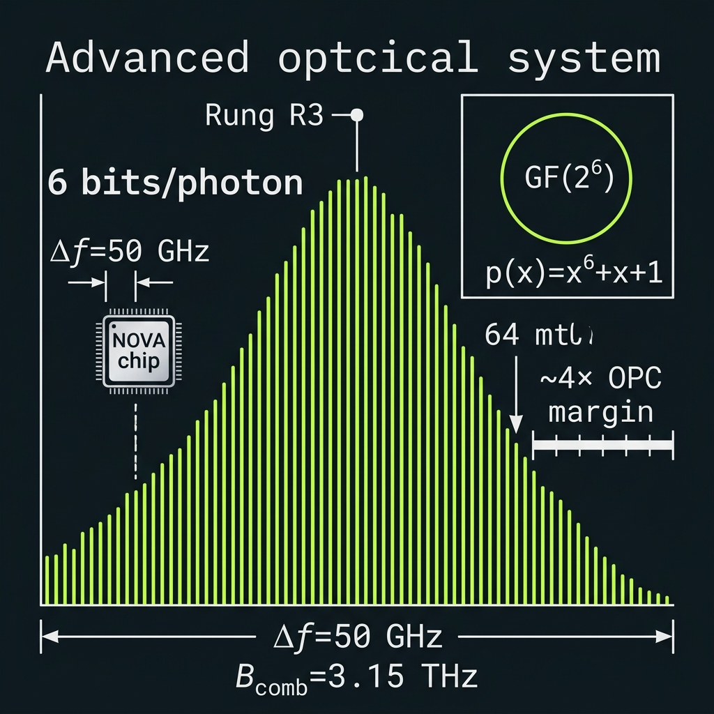
GF(64) = GF(2⁶) field layer
→Physical carrier: d=64 frequency-bin qudit on QUASAR NOVA. Logical algebra: GF(2⁶) — XOR addition, log-table multiply, primitive polynomial x⁶+x+1. Unlocks RS/BCH/LDPC, X₆₄/Z₆₄ stabilizers, mature telecom coding IP. Not base-64 decimal.
6 bits/photon · Δf=50 GHz · B_comb=3.15 THz · ~4× OPC margin
How we do it: 64-line locked comb @ Δf=50 GHz, GF(64) FAU (XOR + GFMUL), 4×16 cascaded AWG demux, RS(63,55) encoder, qudit stabilizer rounds via project-then-detect.
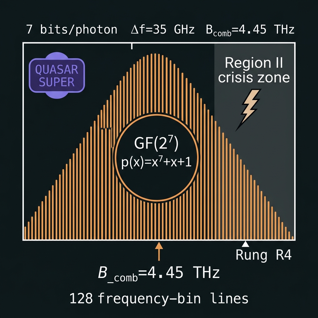
GF(128) = GF(2⁷) — QUASAR SUPER
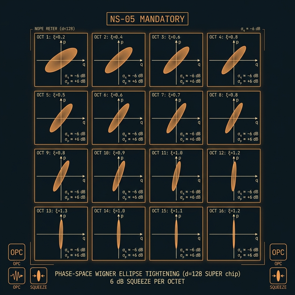
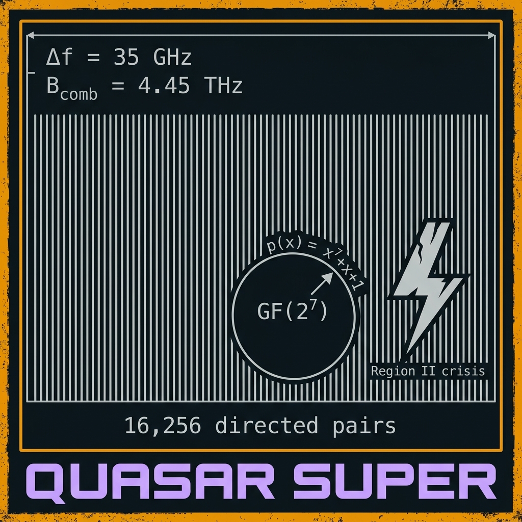
→|ψ⟩ = Σ_{n=0}^{127} c_n|f_n⟩ on a 128-bin carrier. Field layer GF(2⁷) with p(x)=x⁷+x+1 — 7 bits/photon. SUPER sits in QUASAR Region II: the "crisis rung" where one-pass OPC margin tightens to ~2.7× and 16,256 directed phase pairs demand distributed OPC + mandatory squeezing.
Δf=35 GHz · B_comb=4.45 THz · RS(127,119) · [roadmap]
How we do it: 128-tooth comb; 8×16 AWG demux tree; ≥6 dB squeeze per octet; continuous OPC mesh begins here; X₁₂₈/Z₁₂₈ stabilizers with hybrid homodyne+SPAD readout.
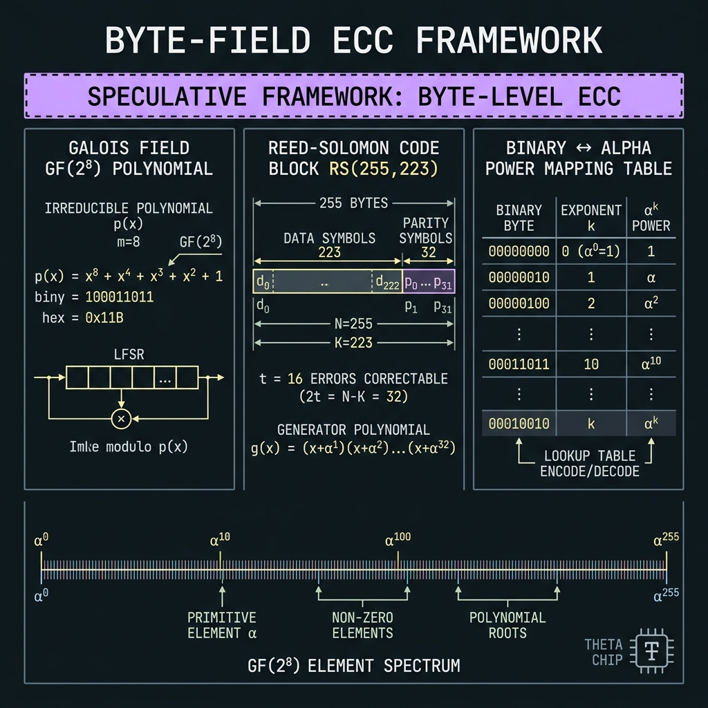
CV/DV GF(256) = GF(2⁸) — QUASAR THETA
→Byte-native symbol field: GF(2⁸) with p(x)=x⁸+x⁴+x³+x²+1 (0x11B) — aligns with RS(255,223), QR, DVB, CCSDS byte algebra. THETA in Region III Q≈1: CV stabilization is co-primary with DV gates; one-pass OPC fails at nominal pitch — continuous mesh + split-band required.
8 bits/photon · Δf=25 GHz · B_comb=6.38 THz · [speculative-framework]
How we do it: 256-line dense comb; 16×16 K×16 demux ladder; ≥10 dB distributed squeeze; global φ₀ calibration plane; RS(255,223) + X₂₅₆/Z₂₅₆ stabilizers; CV-assisted syndrome extraction.
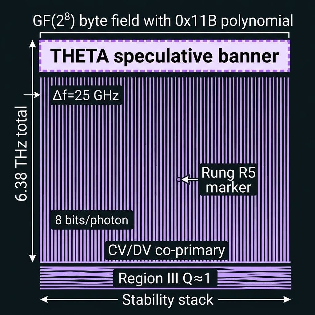
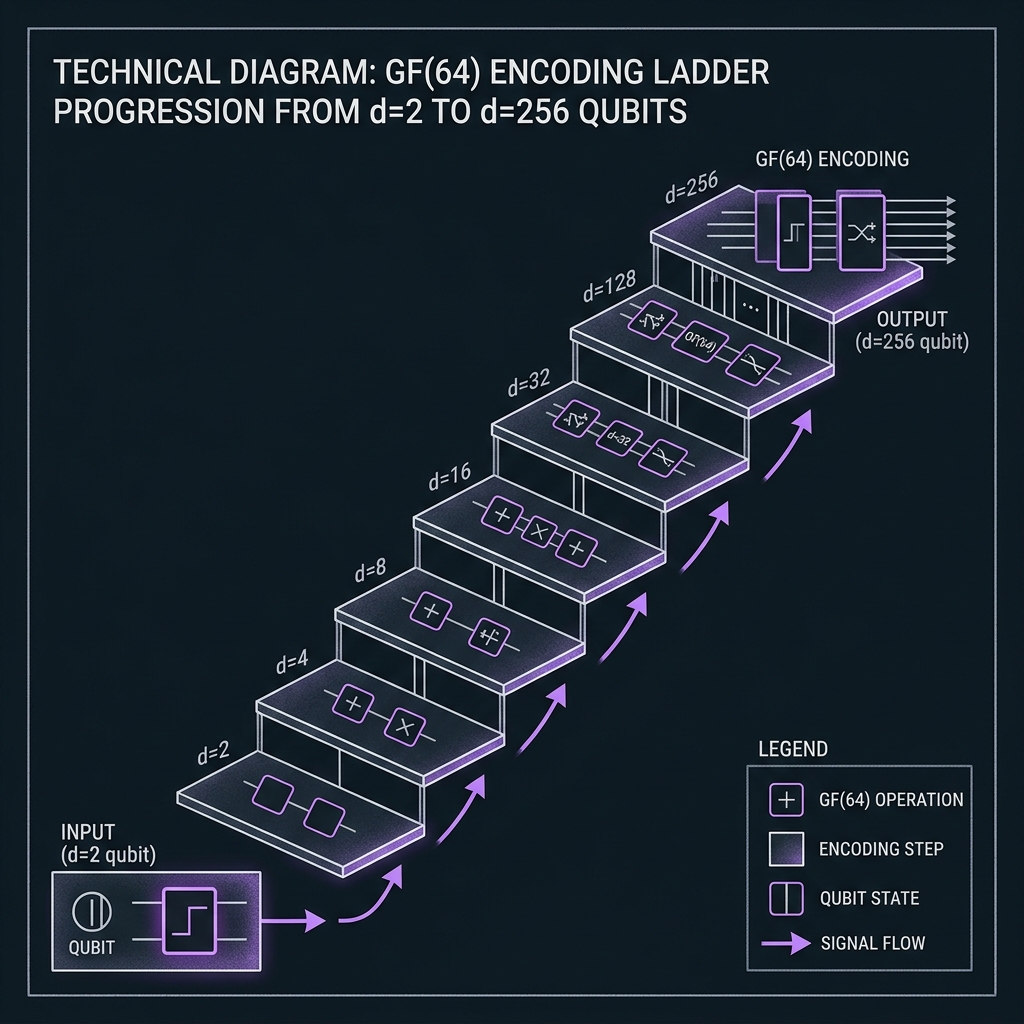 Figure 1
Decimal Quantum Frequency Processor
Native decimal arithmetic in SU(10) — not binary decomposition.
DQFP blocks & opcodes
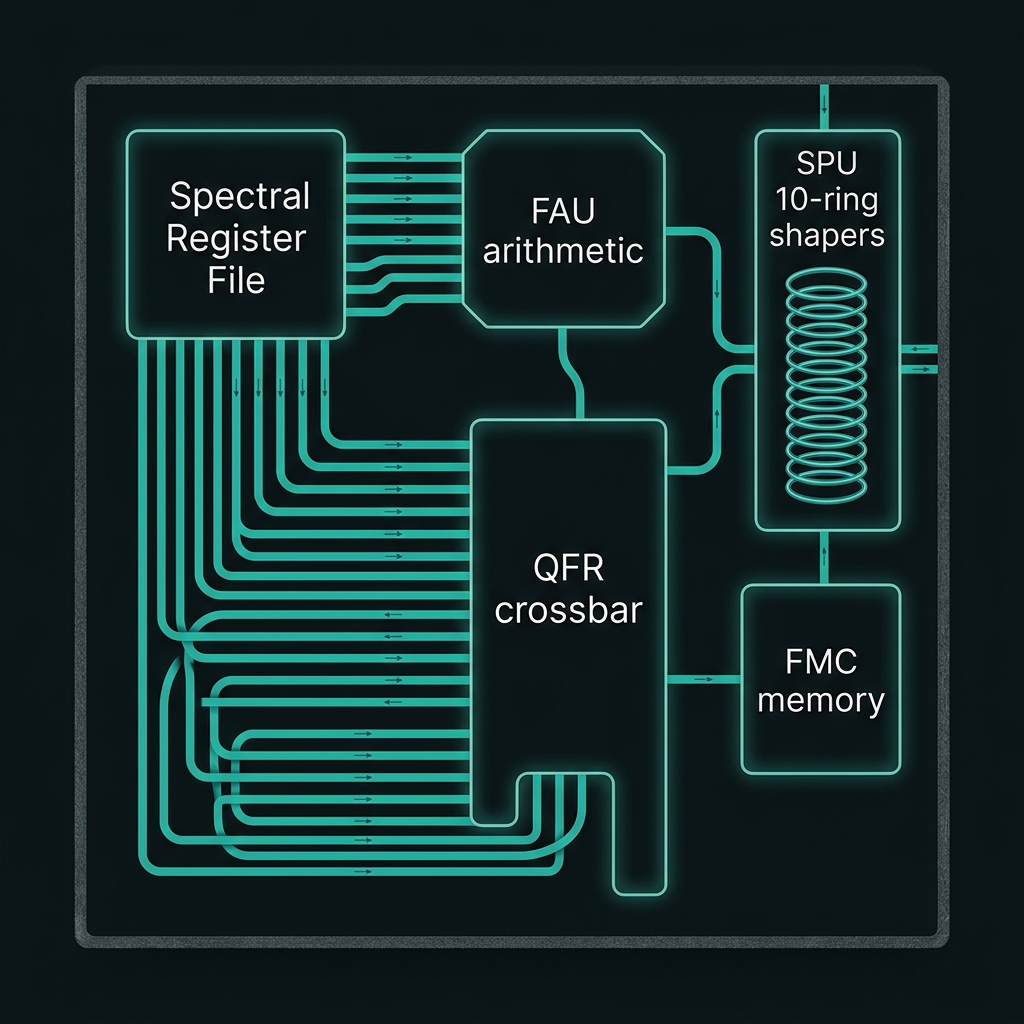
Register file · FAU · SPU · QFR · FMCProcessor architecture
→Spectral Register File R₀…R_N — decits on Δf-spaced comb slices. FAU — decimal add/sub/mul/div mod 10 via frequency translation + spectral interference. SPU — 10-ring microring shaper for Z₁₀ and DFT10. QFR — WDM crossbar for multi-decit ops. FMC — SFWM microring memory banks.
How we do it: Lukens QFP model on TFLN-bonded Si₃N₄; FPGA BRAM microprogram tables drive EOM RF and shaper DAC masks.
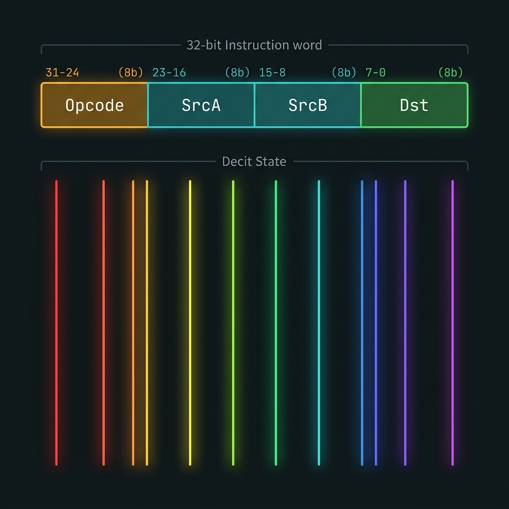
Instruction format & decit primitive
→| Opcode (8) | SrcA (8) | SrcB (8) | Dst (8) | → 32 bits
Decit: |ψ⟩ = Σ_{n=0}^{9} c_n |f_n⟩ , measurement → digit n ∈ {0…9}
How we do it: T-B07 smoke test: DADD R7,R4,R3 on live 50 GHz comb; herald + project-then-detect validates digit readout.
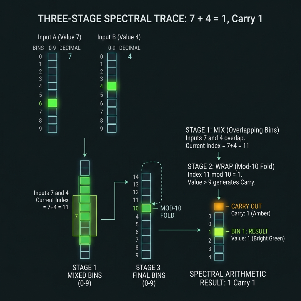
DADD · DSUB · DMUL · DDIV
→Decimal addition mod 10: (R_a + R_b) mod 10 via EOM X₁₀^k frequency translation + shaper wrap masks. Worked example: 7 + 4 = 1 (carry = 1) — three-stage MIX → WRAP → X₁₀ spectral trace.
How we do it: FAU east wing on Si₃N₄ bus; microprogram ROM; OPC brackets every arithmetic macro; SDCLA handles multi-digit carry (§3).
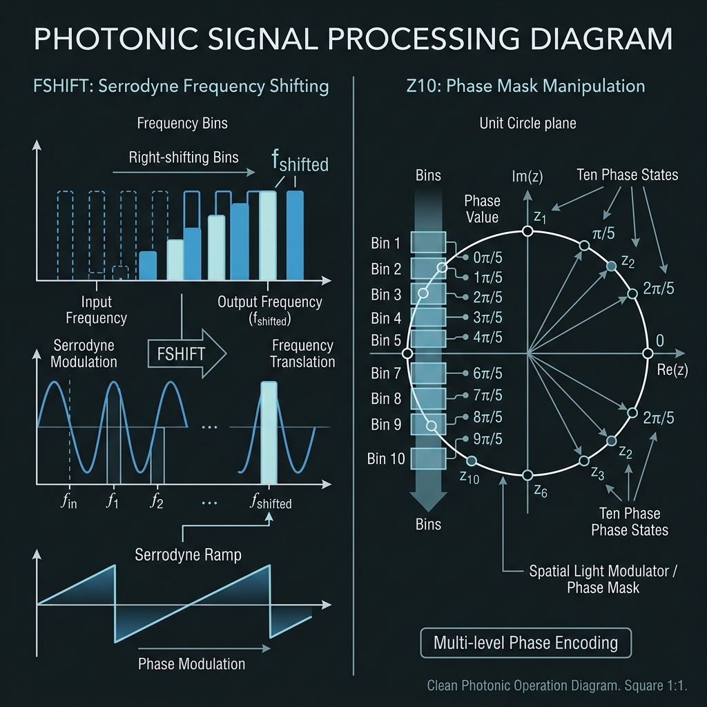
FSHIFT · FCYCLE · PHASE · DFT10
→FSHIFT — |f_n⟩ → |f_{n+k}⟩ via TFLN serrodyne at f_RF = Δf. FCYCLE — native X₁₀ increment. PHASE — Z₁₀: |n⟩ → ω^n|n⟩ on shaper only. DFT10 — decimal quantum Fourier transform; Hadamard analog for base-10.
How we do it: SPU 10-ring bank for PHASE; EOM→shaper→EOM cascade for DFT10 (12–32 QFP sandwiches).
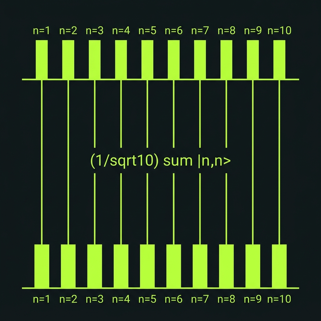
C-DADD · SWAP10 · ENTANGLE10
→Controlled decimal add, register swap, and maximally entangled decit state (1/√10)Σ|n,n⟩. ENTANGLE10 enables teleport-based COPY (no-cloning respected — G44).
How we do it: QFR WDM crossbar + beamsplitter tiles; same hardware as gate mesh, reprogrammed for multi-register ops.
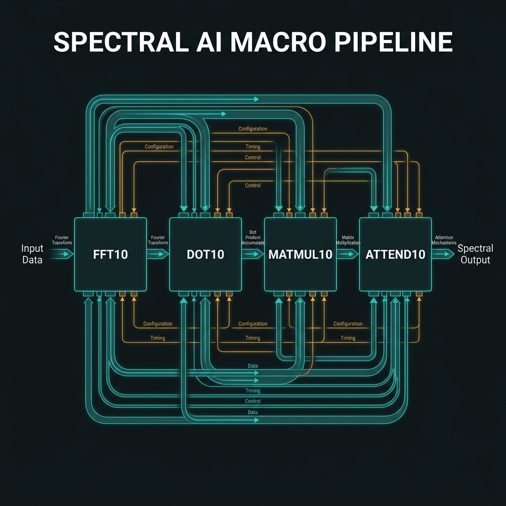
Memory · SYNDROME · DOT10 · MATMUL10
→LOAD/STORE to FMC microring banks; SYNDROME/CORRECT/RESET for decit QEC (ℤ₁₀ stabilizers — distinct from GF(64) L7). AI extensions: DOT10, MATMUL10, ATTEND10, FFT10 as spectral macros. Softmax stays classical in v1.
How we do it: FMC L0–L3 memory tiers; QFP U_k before demux for syndrome extraction; AI macros as firmware compositions over F₁₀ + pointwise multiply.
SDCLA — decimal arithmetic without ripple delay
Carry propagation as spectral interference, not wire routing.
Gᵢ and Pᵢ operators
Gᵢ = 1 iff aᵢ+bᵢ ≥ 10; Pᵢ = 1 iff aᵢ+bᵢ = 9. Carry: C_{i+1} = Gᵢ ∨ (Pᵢ ∧ Cᵢ). All {Gᵢ,Pᵢ} computed in parallel via identical EOM→shaper→EOM GP cells on WDM-separated decit lanes.
How we do it: TFLN beamsplitter GP tiles; shaper masks Θ_G/Θ_P; phase-flag carry encoding to FPGA.
Spectral carry tree
After parallel GP prediction, radix-10 prefix scan resolves carries in ⌈log₁₀ N⌉ tree levels — vs O(N) ripple. For N=8 decits: ~3 QFP depths vs 8 ripple (~2.7×).
How we do it: FAU east wing combine tiles; associative (G,P)⊗ merge at each tree node; fair-comparison discipline vs binary CLA (G15).
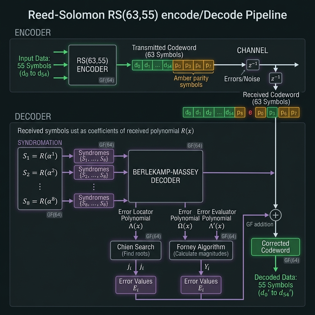
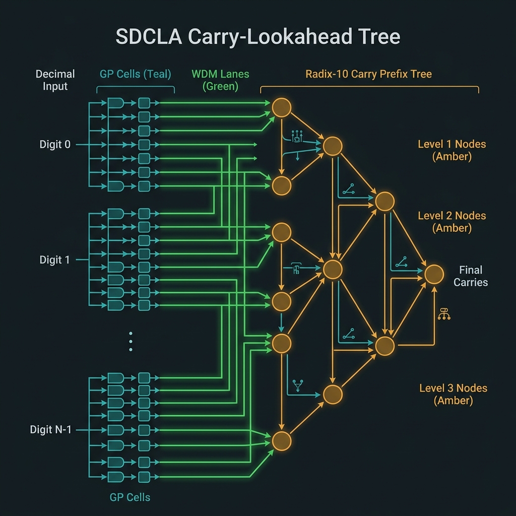 Figure 2
What GF(2⁶) unlocks — and its limits
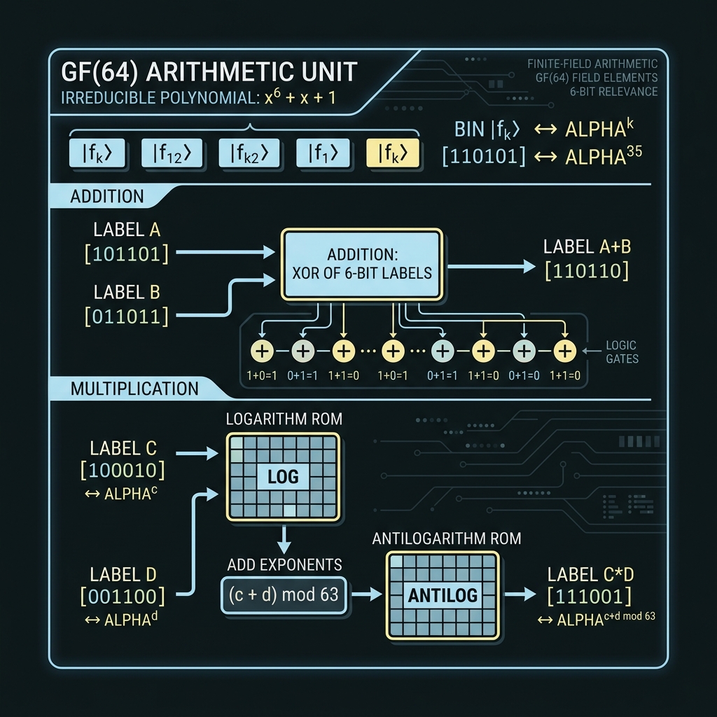
GF(64) subsystems
FAU · RS/BCH/LDPC · stabilizers · SU(64) gatesGF(64) arithmetic unit
→Addition = XOR on 6-bit labels. Multiplication via log/antilog ROM or polynomial convolution mod p(x)=x⁶+x+1. Bins labeled |f_k⟩ ↔ α^k.
How we do it: Reuse DQFP EOM+shaper stack in GF64 mode; electronic shadow on FPGA for validation before full photonic MAC.
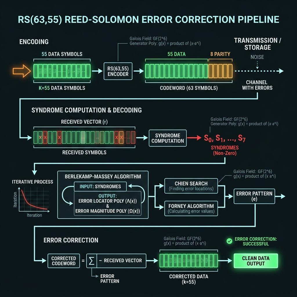
Reed–Solomon · BCH · LDPC
→RS(63,55) default for compute registers; BCH(63,45) for FMC pages; LDPC(4096,3584) for bulk/AI tiles. Syndromes are field elements ∈ GF(64) — not decits, not bin indices.
How we do it: Photonic RSENC on G16 FAU; electronic Berlekamp–Massey decode; herald-aware erasure export from L1.
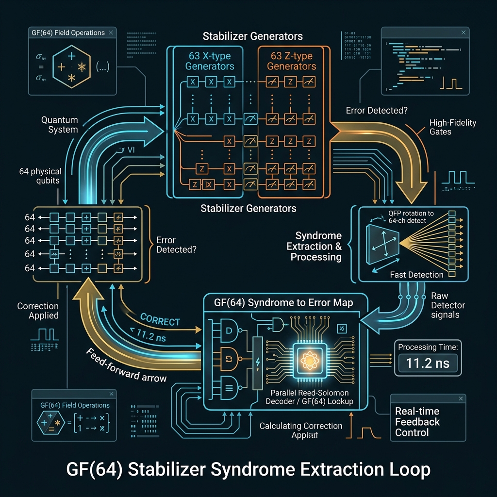
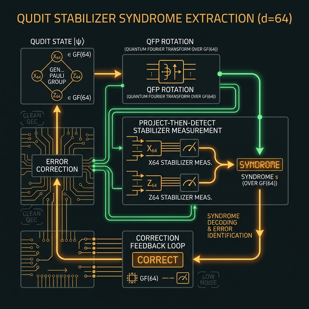
X₆₄ · Z₆₄ stabilizer codes
→63 X-type + 63 Z-type generators per site. Syndrome = QFP rotation U_k → 64-ch project-then-detect → s ∈ GF(64) → CORRECT within ~11.2 ns feed-forward.
How we do it: STAB_LUT BRAM; sparse round scheduling; threshold to-be-modeled (A507 d=64 extension).
Universal gate set & AI mapping
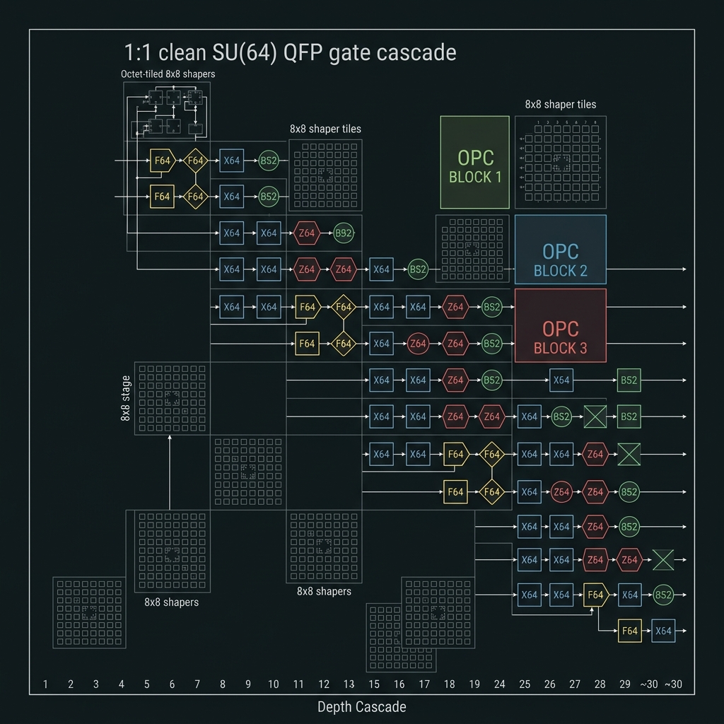
→{X₆₄, Z₆₄, F₆₄, BS₂} generate SU(64). F₆₄ at 12–32 QFP stages. MATMUL₆₄/ATTEND₆₄: FFT64 → GFMUL → XOR accumulate. Production stays Tier A/B (≤32 depth).
How we do it: Octet-tiled 8×8 shaper banks; offline-compiled F₆₄; OPC every 8–12 stages; softmax classical at host.
GF(64) on NOVA is the last rung where one-pass comb-derived OPC sits in a comfortable ~4× margin band and 64-ch SPAD readout suffices. Above d=64 the STAR-PHASER linear paradigm breaks: QUASAR takes over — tighter Δf, mandatory squeeze, hybrid homodyne syndromes, continuous OPC mesh, and calibration that scales as N(N−1) directed phase pairs (16,256 @ d=128; 65,280 @ d=256). See QUASAR framework Law I–II and §10 below. Roadmap
Frequency labels tensor with squeezed qumodes
Squeezing does not change carrier frequency — it tightens the quantum noise floor.
Each comb tooth is a harmonic oscillator: |n⟩_freq ⊗ |ξ_n⟩_CV. DV gates act on the color index; squeezing + OPC act on quadratures within each color. OPC reverses coherent drift (φ→−φ); squeezing attacks quantum uncertainty (sub-SQL syndromes, LIGO analogy).
Phase-squeezed frequency-bin states improve spectral gate fidelity, QEC syndrome measurement, and readout — not an additional radix dimension. Speculative (f_n, r_n) two-DOF encoding is a documented hedge only (G30).
How we do it
- χ⁽³⁾ Si₃N₄ microring squeeze sources (4–7 dB inferred)
- Ge p-i-n balanced homodyne @ 15.3 GHz, pump-split LO
- Dual fork: SPAD (population) + homodyne (phase syndromes)
- GKP/cat/binomial bosonic codes on selected bins (L5)
- Scale: 64 squeeze channels on GF(64) roadmap
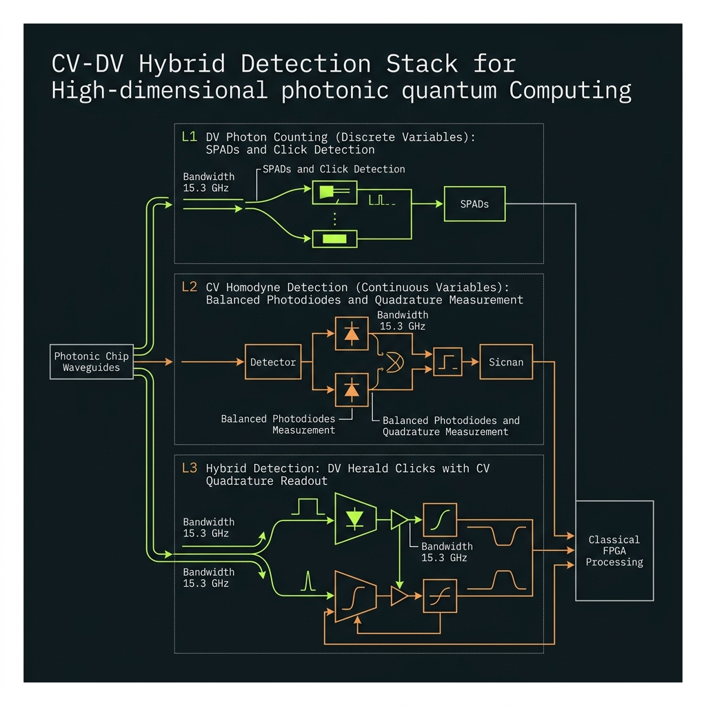 Figure 3
Squeezing requirement vs dimension
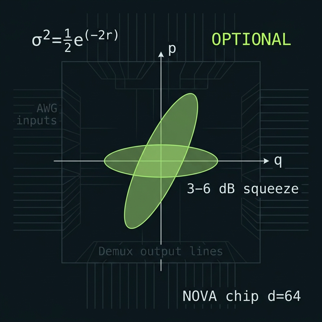
σ² = ½e^(−2r). Optional at GF(64); mandatory from GF(128) upward.
Squeeze staircase
3 dB helpful → 6 dB mandatory → 10 dB distributed3–6 dB squeeze at GF(64)
→χ⁽³⁾ Si₃N₄ microring sources (4–7 dB inferred) tighten phase syndromes and gate fidelity. OPC still carries primary phase hygiene; squeeze is a performance multiplier, not yet mandatory. Roadmap
How we do it: Sparse squeeze allocation on compute octets; Ge homodyne @ 15.3 GHz for Z-syndrome taps.
≥6 dB mandatory per octet
→At SUPER, 35 GHz pitch and 16,256 directed phase pairs collapse OPC margin to ~2.7× WARN. OPC + squeeze mandatory — external precedent: 18 dB TFLN, 7.5 dB TF-PPLN microresonator (2025–2026). Roadmap
How we do it: One squeeze source per octet (16 octets); pump-null schedule; squeeze verifies before grid_valid.
≥10 dB distributed at GF(256)
→THETA Region III: sub-SQL syndromes and GKP-qudit bridges require distributed ≥10 dB across 32 octets with global φ₀ reference. CV sector is co-primary with DV gates — not a sidebar. Speculative
How we do it: Stitched squeeze mesh; continuous OPC boundary layer; tensor |f_n⟩⊗S(r) on every compute bin.
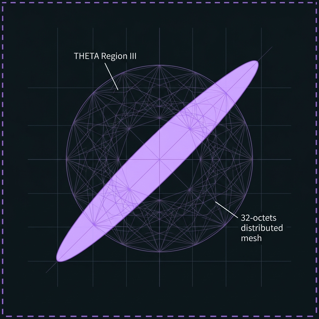
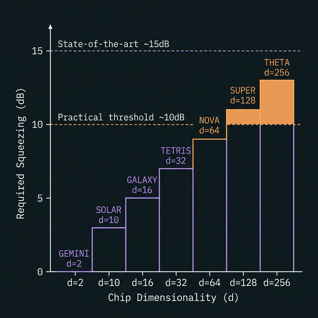 Figure 3a
Project-then-detect at 64 → 128 → 256 channels
Readout tiers
SPAD tree → hybrid homodyne → CV-assisted φ₀64-ch SPAD project-then-detect
→Baseline: QFP rotation U_k → 4×16 AWG demux → warm SPAD array. Population readout for X-syndromes; homodyne on selected Z generators. Designed/target
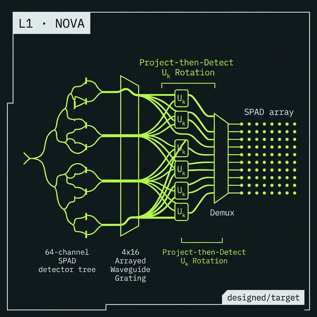
128-ch hybrid homodyne + SPAD
→64 SPAD + 64 Ge homodyne pairs in dual-path syndromes — DV digit + CV Z-syndrome on same demux fork. 8×16 routing tree. Roadmap
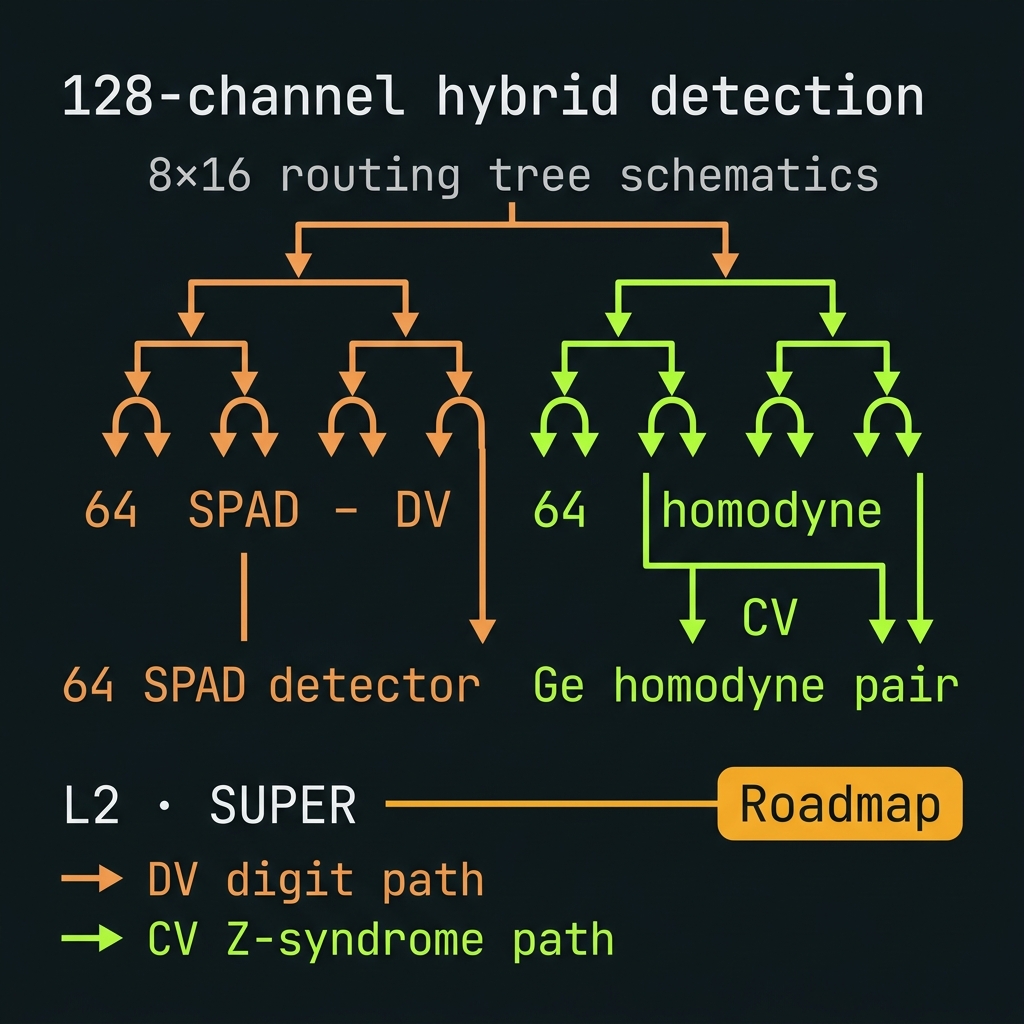
256-ch CV-assisted + global φ₀
→Full tensor |f_n⟩⊗S(r) readout with global phase reference plane; compiler classifies each stabilizer row as SPAD / HOMODYNE / DUAL. 16×16 demux ladder. Speculative
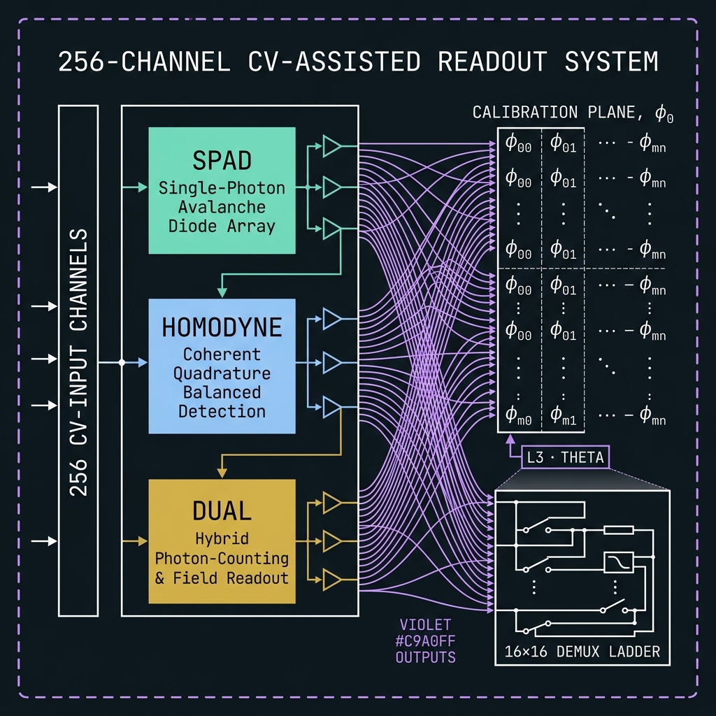
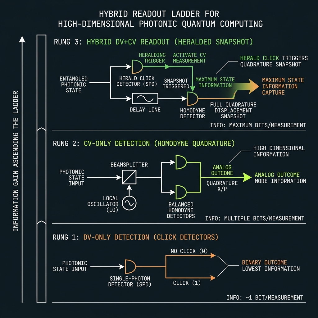 Figure 3b
How we preserve quantum data on the chip
Each layer removes a different error class before accumulation.
Tap any layer. L8 (topological spectral) is speculative; L9 orchestrates refresh across L1–L8.
Preservation hierarchy
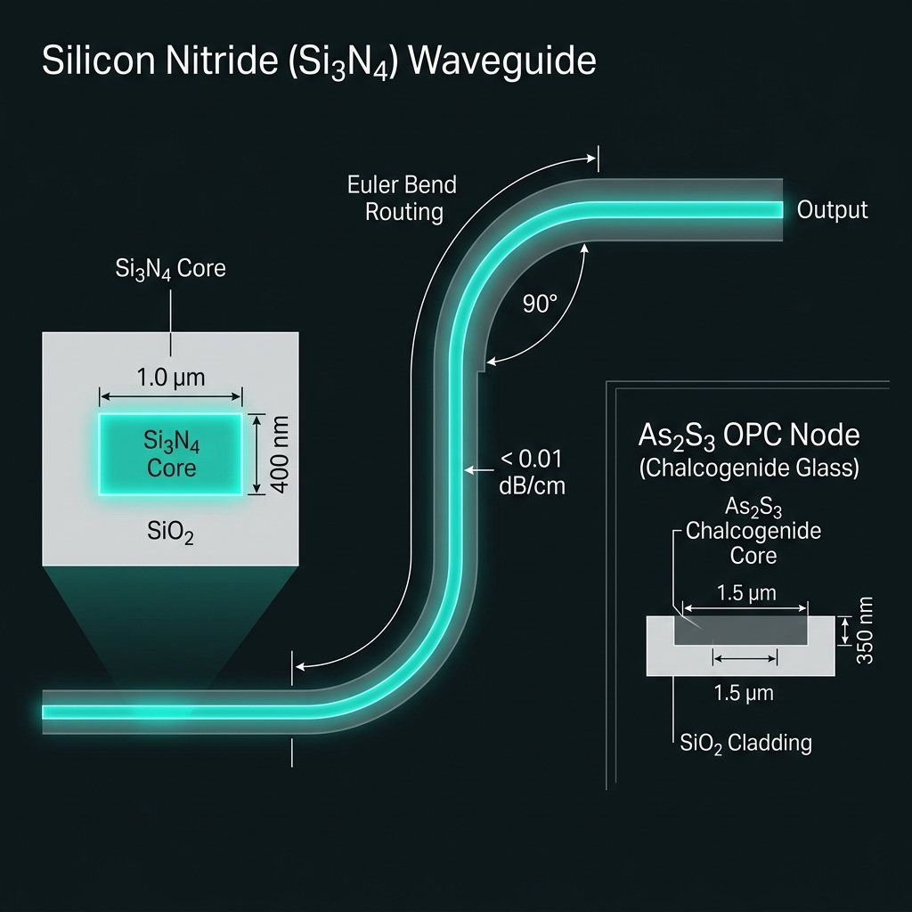
Photon → field symbol → logical qudit → encoded stateUltra-low-loss Si₃N₄
→α < 0.01 dB/cm target; As₂S₃ quarantined to OPC spirals only. Survival S = 10^(−L/10). Herald erasures feed RS decoder.
How we do it: Damascene SiN backbone; Euler bends; split-fab BEOL overlay only at OPC nodes.
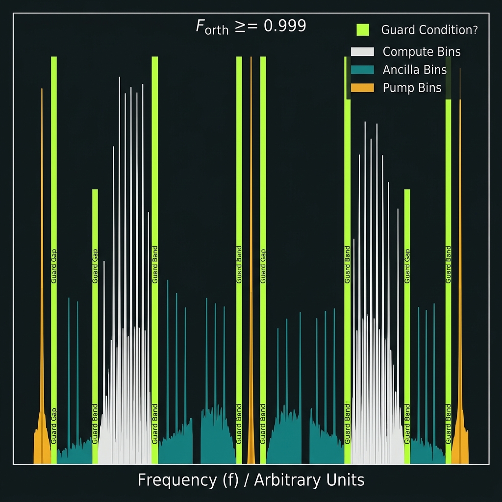
Spectral orthogonality
→Comb locking: SFWM birth coherence + per-tooth heater grid. Guard bands between compute bins, ancilla, pumps. Leakage budget F_orth ≥ 0.999.
How we do it: L0 global → L1 octet → L2 tooth → L3 TED firmware loops; grid_valid gate.
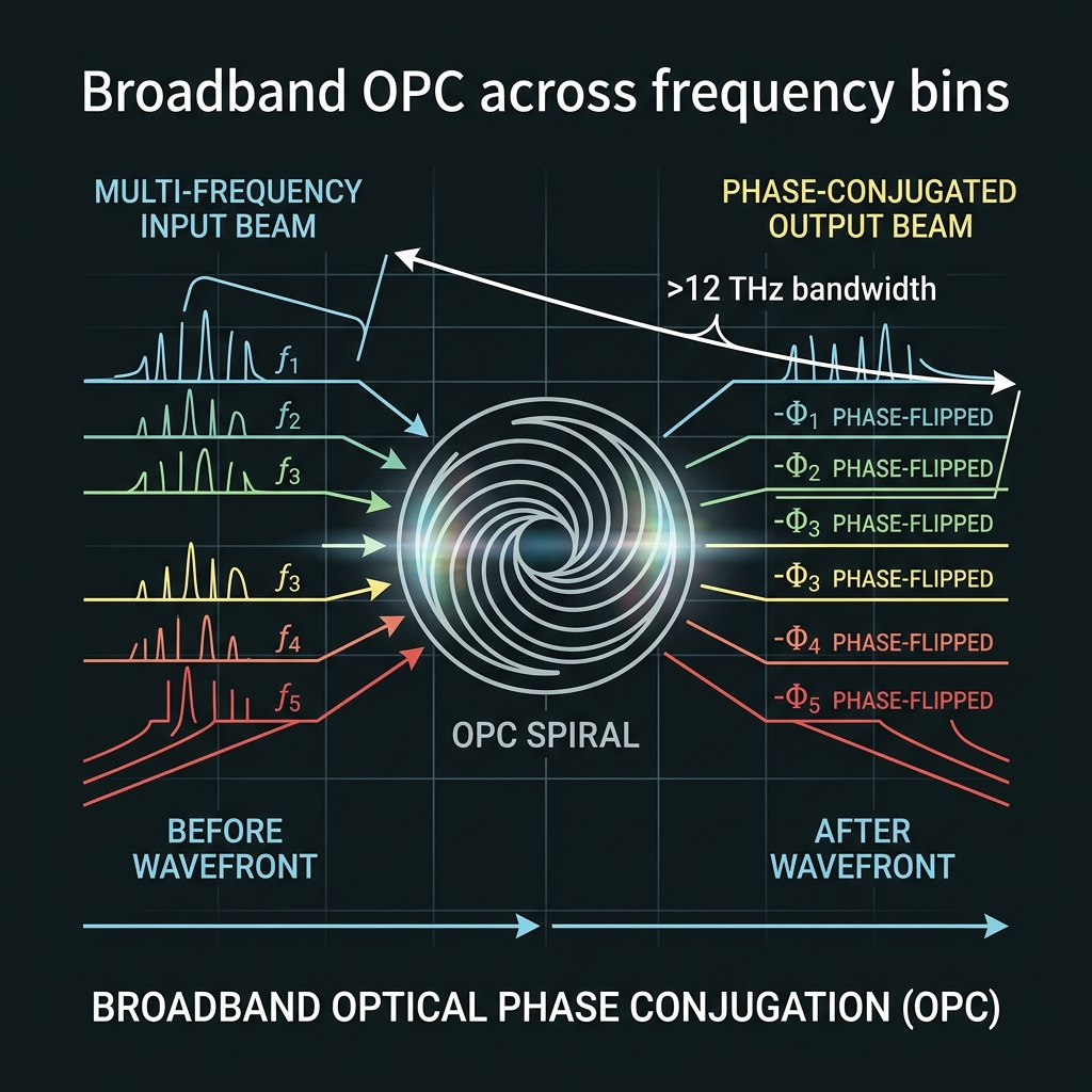
Relative phase + OPC
→Broadband FWM: φ_n → −φ_n for all d bins in one pass. Periodic lattice every ~10 gates; boundary OPC at GAP04 transcoder. Error bounded by interval M, not total depth.
d≥128 stress: One-pass margin WARN @ GF(128); FAIL @ GF(256) — continuous boundary mesh replaces monolithic spiral (§7.1).
How we do it: Hybrid As₂S₃/SiN recirculating spirals; comb-derived pumps (§7).
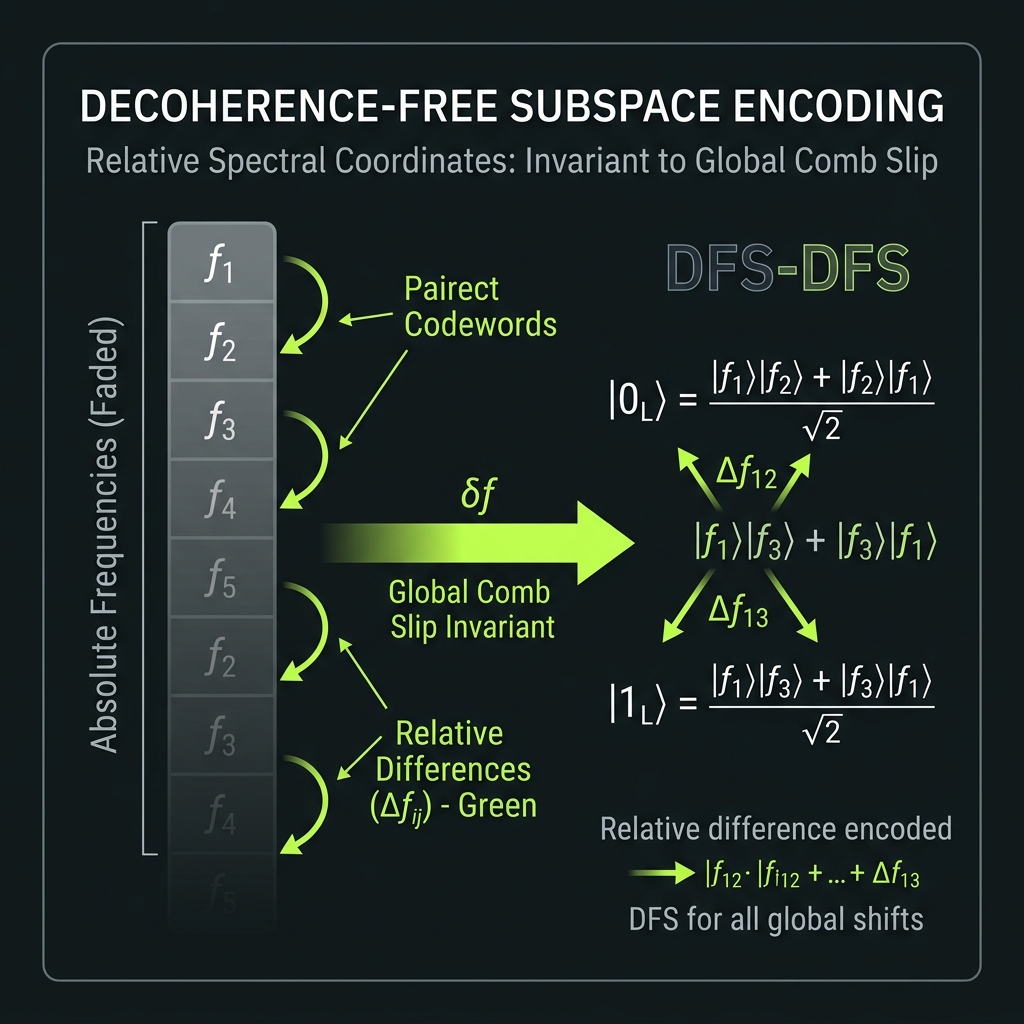
Decoherence-free subspaces
→Encode in relative spectral coordinates (Δn, φ_nm) not absolute lab frequency. Global comb slip handled by CAL_GLOBAL_SLIP retune — not syndrome.
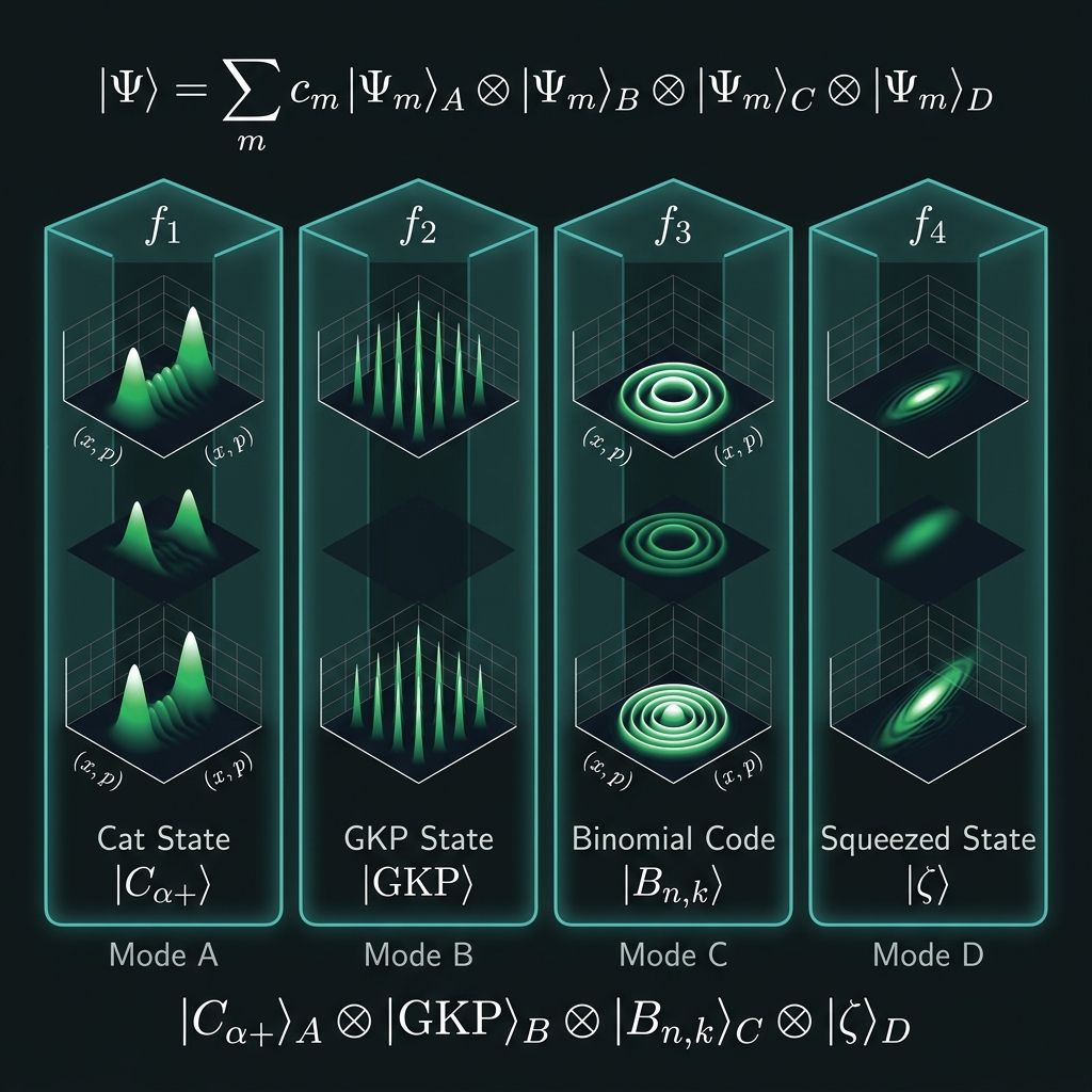
Bosonic encoding
→|n⟩_freq ⊗ |ψ_L⟩_CV — binomial (v1 bridge), cat (Z-biased channel), GKP-qudit (GF(64) roadmap). Sparse allocation policy TBD.
d≥128 stress: Squeeze mandatory per octet (NS-05); GKP-qudit bridges become load-bearing at GF(256), not sparse hedge.
GF(q) classical codes
→RS/BCH/LDPC over GF(64) → RS(127,119) @ GF(128) → RS(255,223) @ GF(256). Photonic parity generation; electronic Berlekamp–Massey decode. Syndromes are field elements — firewall from decit ℤ₁₀ QEC.
d≥128 stress: Syndrome width doubles each rung; photonic encode stays on-chip, BM decode stays electronic.
Qudit stabilizer codes
→X_d/Z_d rounds via QFP project-then-detect: 126 → 254 → 510 generators per site as d climbs. OPC biases Z-errors; digital qudit QEC handles residual. Not a replacement for OPC.
d≥128 stress: Hybrid readout (§5.2) required; stabilizer rounds interleave with L9 refresh slots.
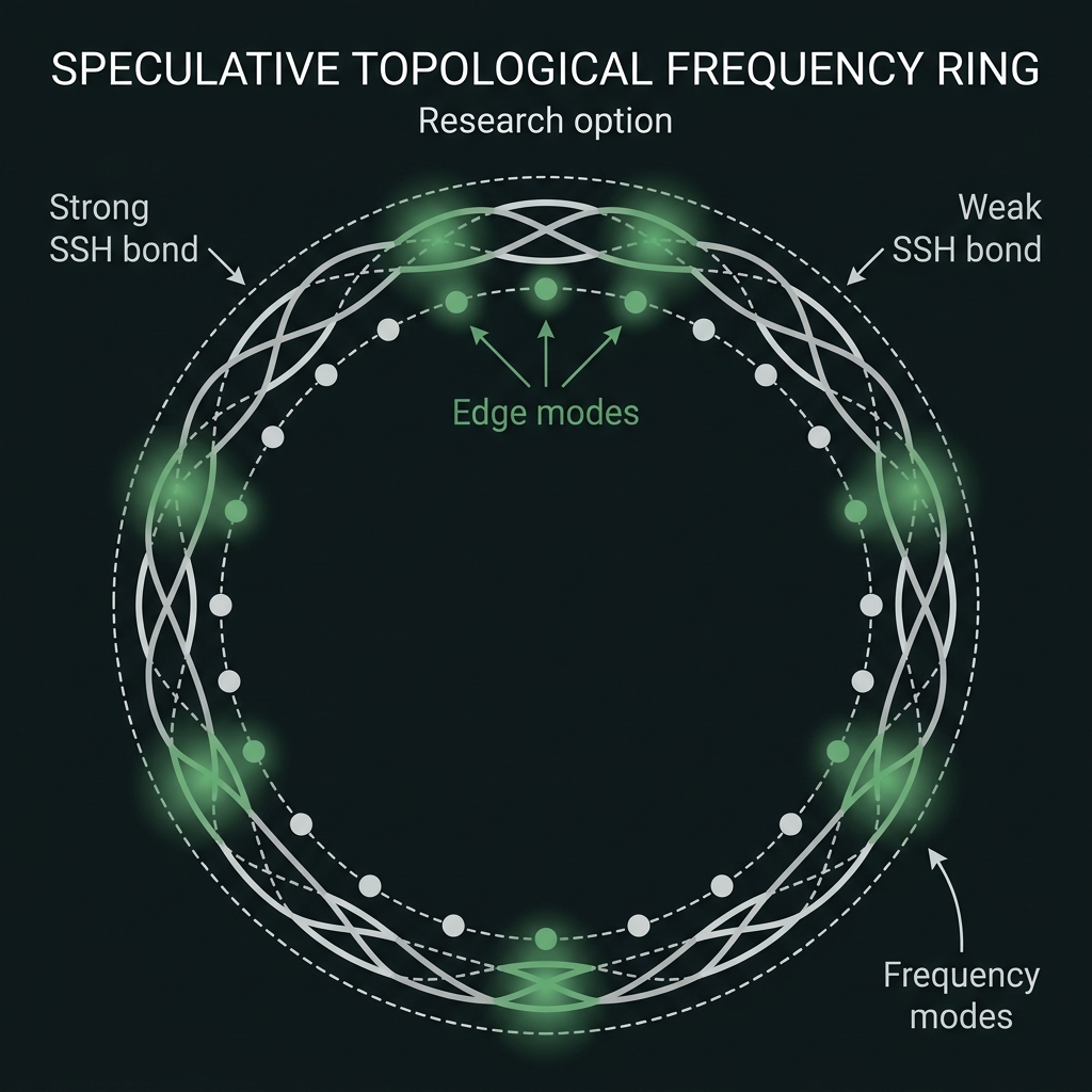
Topological spectral ring
→SSH dimer couplers, Lieb zero-modes, NHT-OPC ring closure — research option only. Kill criterion T-G39-01. Not v1, not gating.
Dynamic spectral refresh
→Five synchronized clocks: gate OPC, FMC DRAM, RS re-encode, bosonic rounds, stabilizer slots. G40 firmware arbiter — coherent DRAM refresh analogue.
d≥128 stress: Refresh interleaving becomes tighter; continuous OPC mesh shares the same arbiter as squeeze pump nulling.
How we do it: refresh_state BRAM; compiler RefreshPass; priority arbiter on photonic bus.
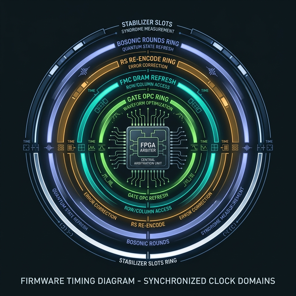
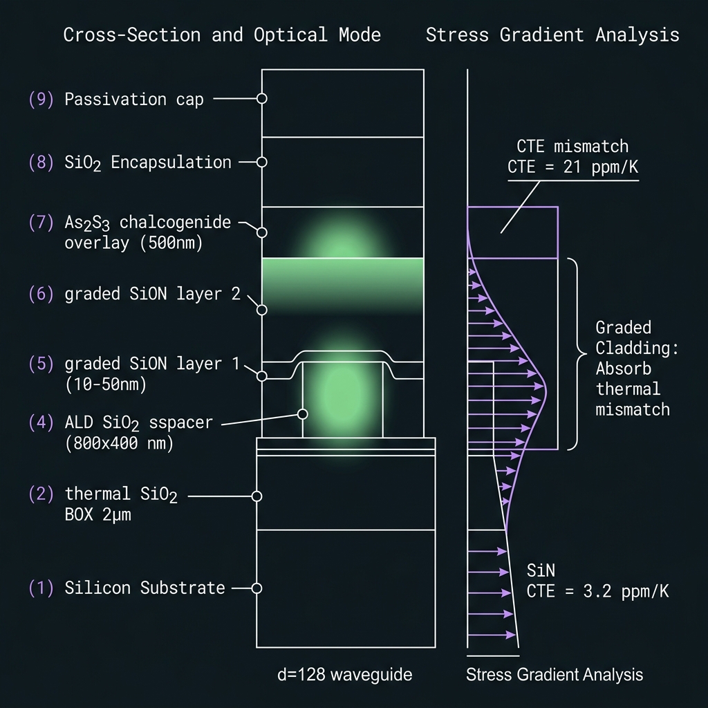 Figure 2a
What the pump does — and how OPC works with it
ωᵢ = 2ωₚ − ωₛ · φ → −φ
E_s = A_s e^{iφ_s}  →  E_i ∝ A_s e^{−iφ_s}
Pump supplies energy + phase reference — not quantum information.
OPC is unitary Bogoliubov evolution — not cloning (no-cloning theorem).
How we do it: Hybrid As₂S₃/SiN spiral; pump in 7.4 THz Raman-null window; ≥110 dB pump rejection; η scales ~P_pump².
Teeth as pumps — one coherent source
Reserve interior comb teeth as degenerate FWM pumps for neighbors. Logic channels, memory, and OPC pumps share SFWM birth coherence — no independent laser sync. 8 pump sites at d=10; 62 at d=64. Spectral re-mapping returns idler to GF(64) α^k grid.
How we do it: opc_pump_mask firmware; octet-stagger if inter-pump crosstalk > −25 dB; f₆₃ guard (α⁶³=α⁰).
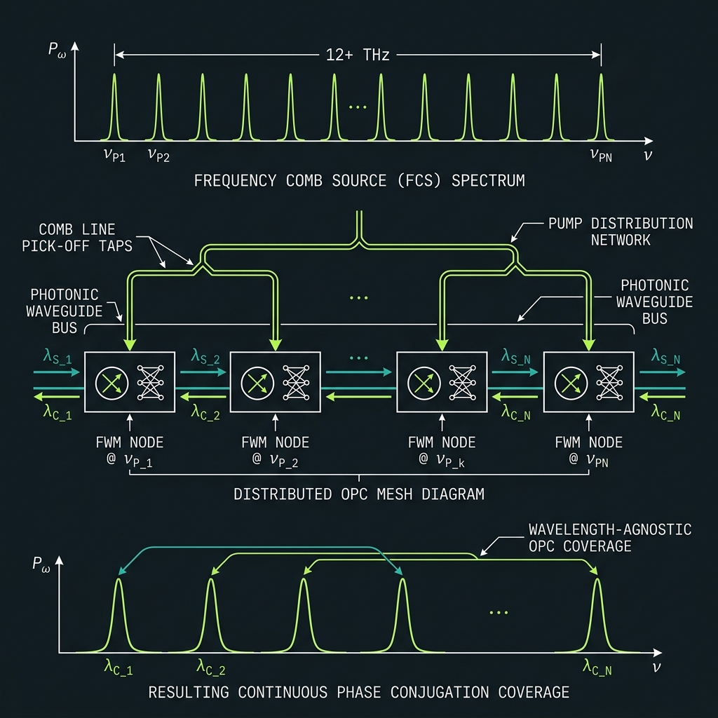 Figure 4
One-pass comfort → WARN → FAIL
Law I: m_margin = B_OPC / B_comb. Continuous mesh when one-pass fails.
~4× comfortable
Δf=50 GHz · B_comb=3.15 THz. Monolithic one-pass OPC on hybrid As₂S₃/SiN spiral covers all 64 bins. Last rung where periodic lattice alone suffices.
~2.7× tight
Δf=35 GHz · B_comb=4.45 THz. SUPER needs distributed OPC cells every Λ=2–5 mm + mandatory squeeze. Comb-derived pumps staggered per octet.
How we do it: GALAXY sparse OPC cells → NOVA periodic lattice → SUPER distributed mesh → THETA continuous boundary layer (Λ cells, comb-derived pumps, split-band). Si₃N₄ FWM bands ~1–6 THz demonstrated; QLT hybrid >12 THz remains to-be-tested (T9).
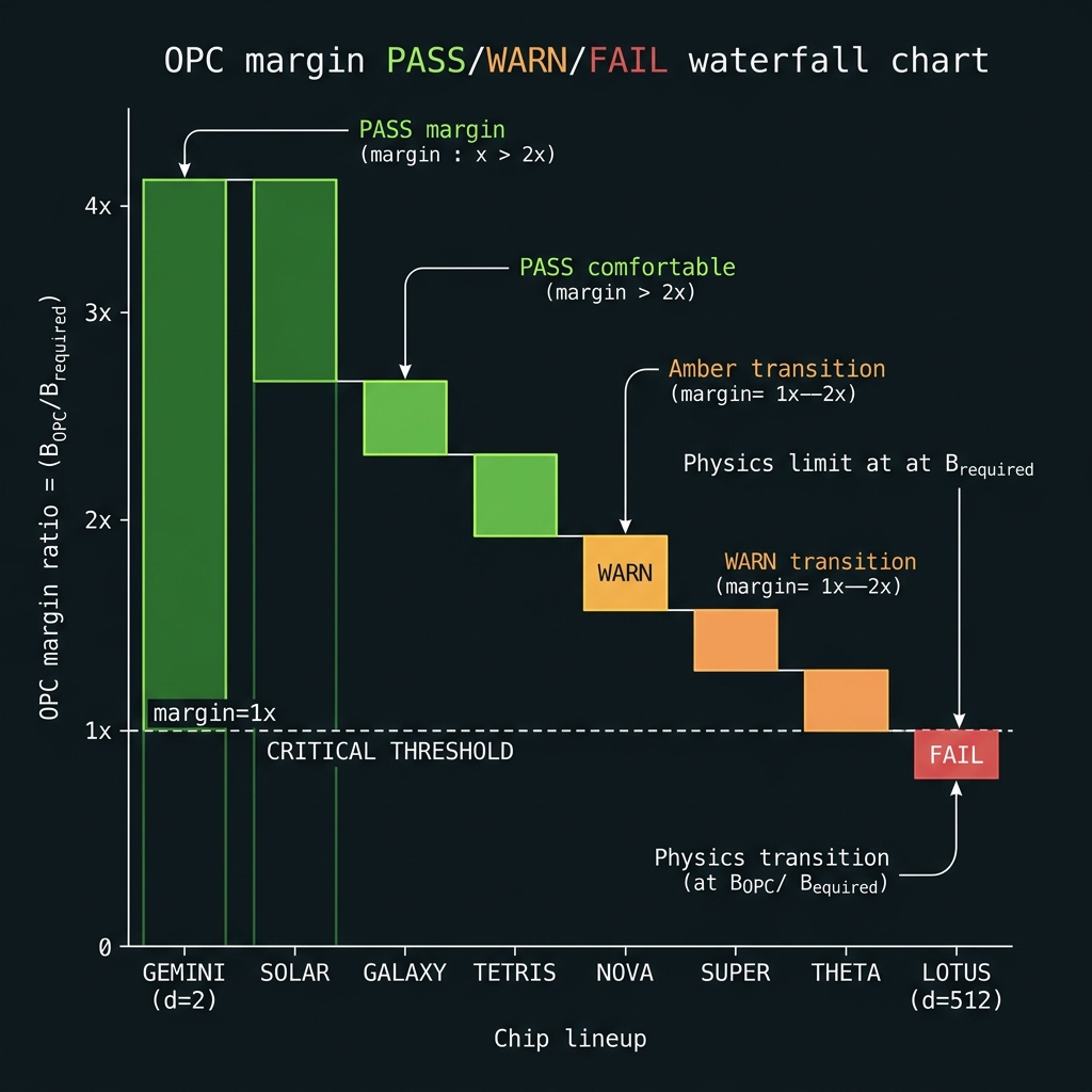 Figure 4a
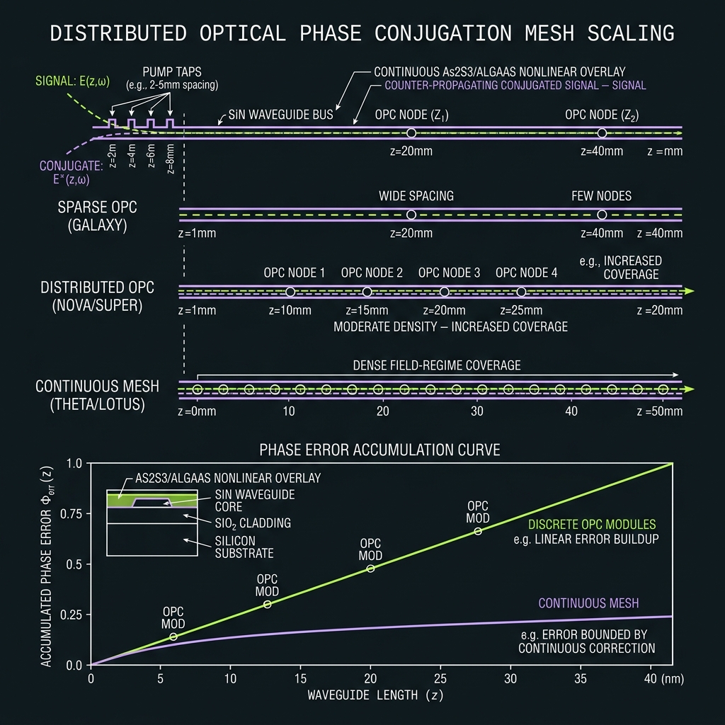 Figure 4b
GF(64) tile on the QLT process flow
Same materials stack as the decit. Scaling d=10 → d=64 is a manufacturing problem solved by three physical levers — not a new platform.
64-line microcomb & octet QFP
R≈480 µm SFWM ring or EO-comb @ Δf=50 GHz (3.15 THz span). 8× octet-tiled TFLN EOM → 8-ring shaper cascades. Same B07 materials stack as decit — scale channels, not platform.
Wafer scatter + thermal trim
Accept 5–15% resonance scatter; lock every tooth with hierarchical heaters (L0 global → L1 octet → L2 tooth → L3 TED). T-G47 signoff matrix.
64-ch demux + dual detection
Cascaded 8×8 AWG; warm SPAD array for digit read; Ge homodyne for phase syndromes. Project-then-detect for any basis. F_read ≈ 0.998 cascaded target.
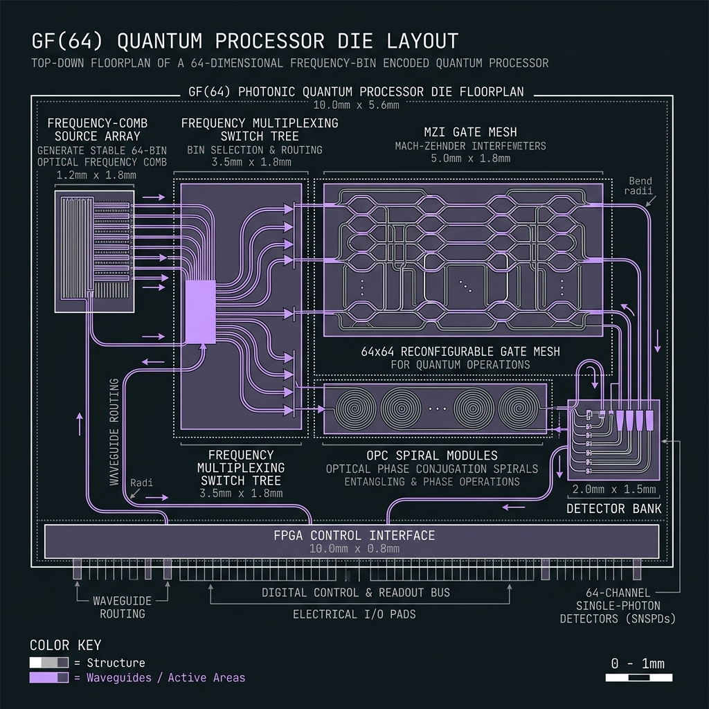 Figure 5
Three levers — d=10 through d=256
Tap any lever. None of this is a new materials stack — it is more of the same device, cascaded routing, and active calibration. Columns show scaling at d=64 (NOVA), d=128 (SUPER), and d=256 (THETA). [roadmap / speculative-framework — Rungs R3–R5, not shipped]
| Lever | d=64 NOVA | d=128 SUPER | d=256 THETA |
|---|---|---|---|
| L1 Modulators | 12–32 EOM sandwiches · ~32 RF tones | 32–48 · 16 octets · 48 RF tones | 48–64+ · 32 octets · 64 tones |
| L2 Routing | 4×16 AWG @ 50 GHz | 8×16 @ 35 GHz | 16×16 @ 25 GHz DWDM |
| L3 Calibration | N(N−1)=4,032 pairs · ChiL/octet | 16,256 pairs · ChiL++ | 65,280 pairs · global φ₀ plane |
Scaling levers
More modulators · larger routing · better calibrationMore modulators — deeper QFP cascade
→GF(64) is the same TFLN modulator, used more times. Named Tier-A/B gates compile to 12–32 EOM→shaper→EOM sandwiches (vs 3–5 for the decit), driven by a harmonic RF bus of up to ~32 tones (f_m = m·Δf) on one segmented traveling-wave modulator. At d=128/256 depth grows to 32–48 → 48–64+ sandwiches with 16 → 32 octet shaper tiling. Field precedent: 256-channel TFLN arrays and 600+ phase modulators on 200 mm wafer [demonstrated].
How we do it: Segmented TFLN bond (Vπ·L ≈ 2.5 V·cm); octet shaper banks; As₂S₃ OPC every ~10 stages; RF tables frozen in FPGA BRAM. Roadmap @ d≥128.
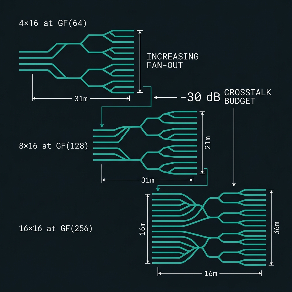
Larger routing networks — K×16 ladder
→Scale by multiplying 16-ch AWG blocks, not one giant demux: 4×16 (NOVA @ 50 GHz) → 8×16 (SUPER @ 35 GHz) → 16×16 (THETA @ 25 GHz DWDM). Each level: octet add-drop → AWG fan-out → Vernier trim, targeting ε ≤ −30 dB cascaded crosstalk. 3D interlayer crossings cut per-crossing loss ~100× [demonstrated].
How we do it: EO reconfigurable TFLN Vernier filters for ns trim; herald switch tree replicated per octet; AWG slices co-calibrated with shaper octets. Roadmap @ d≥128.
Better calibration — N(N−1) pairs → φ₀
→Pairwise phase budget scales N(N−1): 4,032 @ d=64 → 16,256 @ d=128 → 65,280 @ d=256 (directed convention). Thermal matrix grows 64² → 128² → 256². Mode escalates: ChiL/octet → ChiL++/cross-octet → global φ₀ plane at THETA.
How we do it: Chip-in-the-loop self-calibration (O(kN)→O(1) in ~10 iterations) [demonstrated]; grid_valid gate blocks compute until |Δf_err| < 0.5 GHz; WDM drops co-trimmed with shaper octets. Speculative @ φ₀ plane.
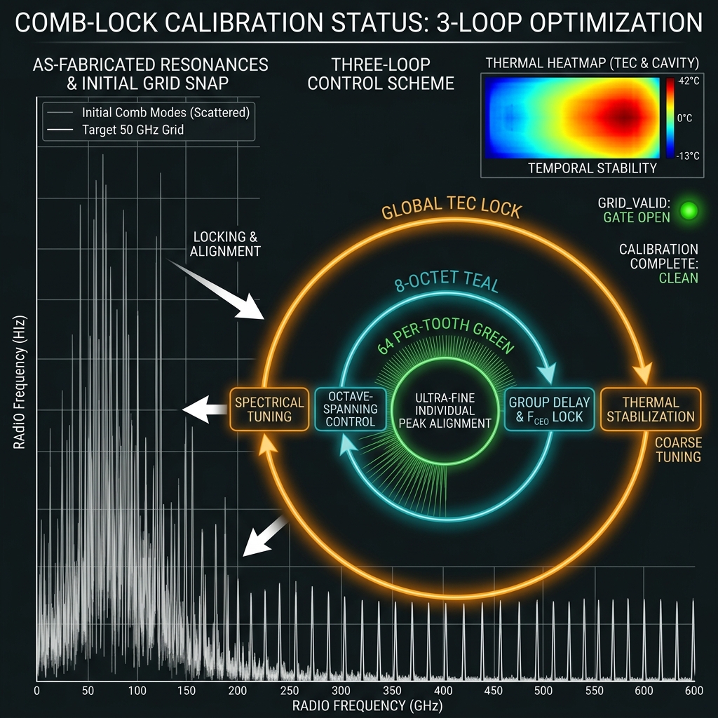
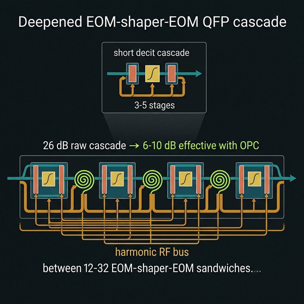 Figure 6
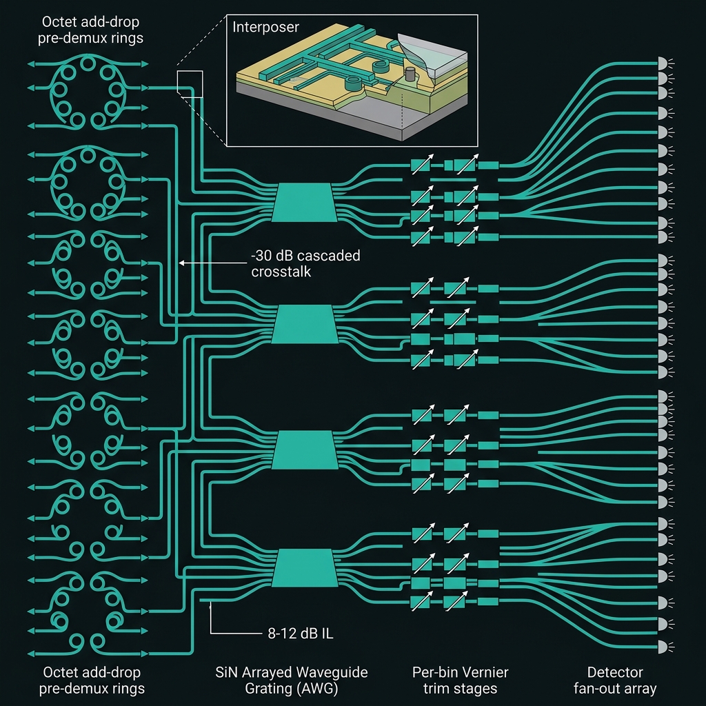 Figure 7
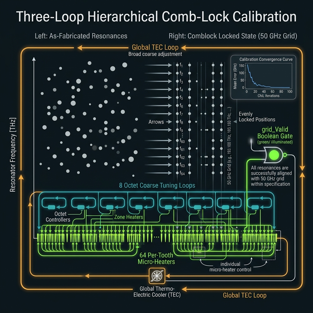 Figure 8
The CV/DV road to GF(256)
Synthesis: why the ladder continues, what changes at each crisis rung, and where to read deeper.
| Rung | Chip | Δf | B_comb | Region | OPC margin |
|---|---|---|---|---|---|
| R3 GF(64) | NOVA | 50 GHz | 3.15 THz | Region I | ~4× PASS |
| R4 GF(128) | SUPER | 35 GHz | 4.45 THz | Region II | ~2.7× WARN |
| R5 GF(256) | THETA | 25 GHz | 6.38 THz | Region III Q≈1 | mesh required |
Brand boundary at d=64: TETRIS → NOVA; STAR-PHASER linear paradigm → QUASAR field-computing architecture. Q-metric tracks coherence budget vs dimension — see QUASAR framework §4.
Extension topics
Encoding · CV · OPC · QEC · routing · applicationsR4 — GF(2⁷) on 128 bins
→7 bits/photon; p(x)=x⁷+x+1; RS(127,119); 16,256 directed phase pairs. Crisis rung where squeeze + distributed OPC become mandatory. SUPER chip page · Roadmap
R5 — byte-native GF(2⁸)
→8 bits/photon; 0x11B polynomial; RS(255,223) aligns with QR/DVB/CCSDS byte algebra. CV stabilization co-primary. THETA chip page · Speculative-framework
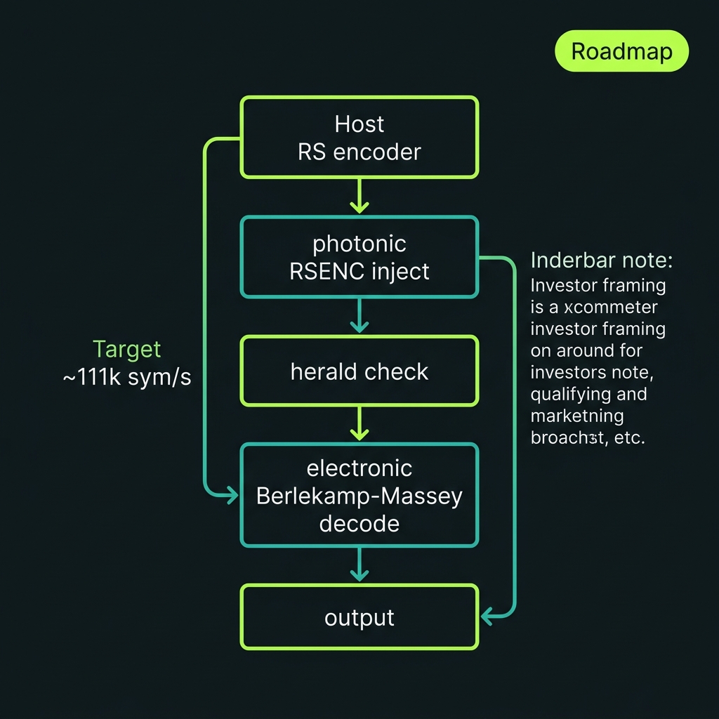
GF(256) coding payoff
→Hybrid classical–quantum byte pipeline: host RS → photonic RSENC → herald → electronic BM decode. RS(255,223) streaming demo concept (~111k sym/s target). Investor framing: GF(256) is where telecom byte IP meets photonic qudit carriers. Roadmap
From roadmap to today's platform
The v1 machine is base-2 dual-rail. See the full photon journey, manufacturing path, and patent portfolio.